
Shallow depth back lit illuminated signage

a backlit, illuminated technology, applied in the direction of point-like light sources, vehicle seats, spectral modifiers, etc., can solve the problems of significant power consumption, significant power consumption, and the inability to accurately reflect light, so as to improve luminance uniformity and improve luminance uniformity. , the effect of significant power reduction

Inactive Publication Date: 2004-11-23
3M INNOVATIVE PROPERTIES CO
View PDF17 Cites 15 Cited by
  • Summary
  • Abstract
  • Description
  • Claims
  • Application Information

AI Technical Summary

Benefits of technology

What the art of lighted signs needs is a more compact, particularly in the thickness dimension (i.e., return depth), and low maintenance back lit illuminated sign, especially a back lit sign suitable for use on a vehicle (e.g., an automobile, bus, truck, train, airplane, watercraft and aircraft).
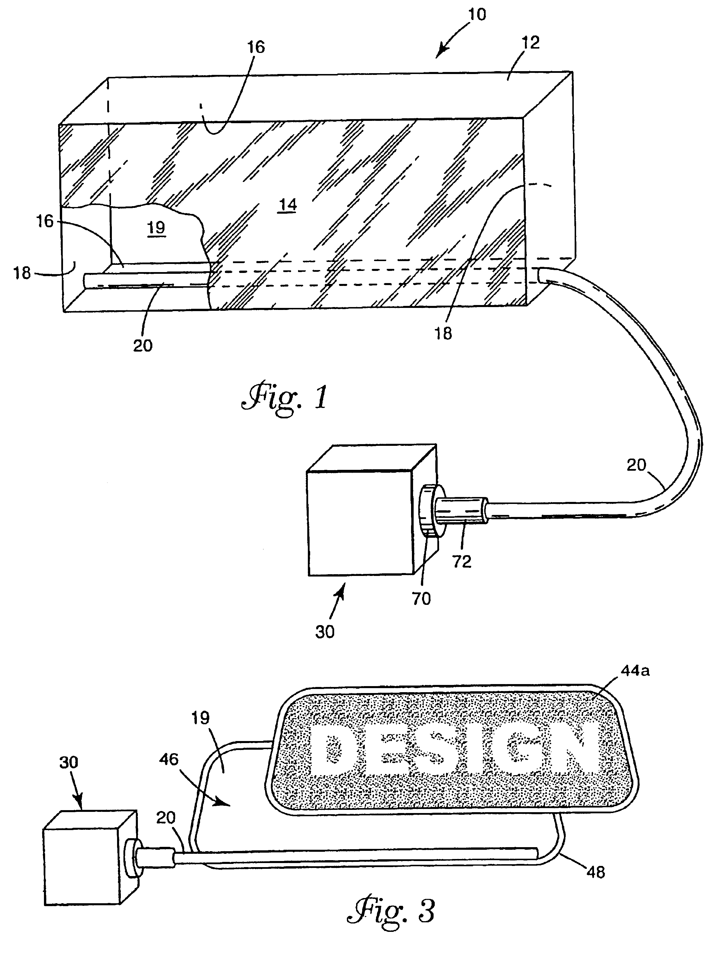
One aspect of the invention is a shallow back lit illuminated sign comprising a housing, a light source and at least one side-light emitting fiber. The housing has a sign face and an interior surface that includes a back surface. The sign face has an illuminated area (i.e., an area of the sign face that will be illuminated) through which light from inside the housing can be diffusely transmitted out of the housing. At least a portion, and preferably most, if not all, of the interior surface is diffuse reflective enough to provide luminance uniformity to the sign. Preferably, the interior surface is sufficiently diffuse reflective to also provide luminous efficiency (i.e., ratio of the amount of light transmitted out of the sign to the amount of light emitted from the fiber(s)) to the sign. The back surface is located at a depth from the sign face, and the sign has a large aspect ratio.
The light source is suitable for supplying light to a light fiber. It is desirable for the light source to be located outside of the housing, but not so far from the housing as to result in an objectionable loss in the efficiency of the fiber (i.e., requiring significantly more power to operate properly). One or more side-light emitting fibers are connected so as to receive light from the light source and are mounted within the housing so as to significantly limit the amount of emitted light, from the fiber(s), that travels directly to the sign face (i.e., that does not reflect at least once off of a diffuse reflective surface before traveling to the sign face). These fibers can be the rigid or flexible type.
The amount of emitted light that travels directly to the sign face is considered significantly limited when there are no visually apparent (with normal contrast sensitivity) and undesirable or offensive "hot spots" on the sign face. To help prevent such direct travel of the emitted light to the sign face, it is desirable for the side-light fiber(s) to be located on the interior surface of the housing, with the light being emitted from the fiber(s) at a narrow enough angular distribution (e.g., 5-20 degrees) that the emitted light travels in a direction generally parallel to the sign face, while allowing incidence on the back surface and other portions of the interior surface.
The diffuse reflective portion(s) of an interior surface of the housing captures the lumens of light from the light source or those lumens of light reflecting back from a diffusing panel or sides and backs of the housing (e.g., a light cabinet) and re-directs such light toward the viewer, thereby providing luminance uniformity on the translucent surface of the sign face.
The reflectivity of the film can be controlled to provide desired power consumption reductions, as well as improved luminance uniformity, according to the needs of those skilled in the art of signage construction. An improvement in luminance uniformity can also provide significant power reduction for a sign. Thus, both the utility and aesthetics of a sign can be addressed by the invention.

Problems solved by technology

It is desirable for the light source to be located outside of the housing, but not so far from the housing as to result in an objectionable loss in the efficiency of the fiber (i.e., requiring significantly more power to operate properly).
The amount of emitted light that travels directly to the sign face is considered significantly limited when there are no visually apparent (with normal contrast sensitivity) and undesirable or offensive "hot spots" on the sign face.

Method used


Image

  • Shallow depth back lit illuminated signage
  • Shallow depth back lit illuminated signage
  • Shallow depth back lit illuminated signage

Examples


example 1

The initial prototype was developed for laboratory measurements to reduce the concept to practice. It was constructed by bending standard aluminum sheet metal into a rectangular box 16".times.79".times.2". The 5 metal box sides were lined with a pressure sensitive adhesive (psa) backed TIPS film. The sign face was constructed from TiO.sub.2 titanium dioxide loaded 6.4 mm PMMA poly(methyl methacrylate) sheet stock with a diffuse reflectivity of approximately 60%. The sign illumination was created using a side extraction light fiber and a remote light source. The fiber consisted of a 12 mm diameter light fiber core manufactured by 3M. A 1 mm wide stripe of TiO.sub.2 vinyl film with pressure sensitive adhesive (Scotchcal.TM. Film, manufactured by 3M company, St. Paul, Minn.) was applied to the length of the fiber to provide side extraction. The fiber was then covered by a heat shrinkable fluoropolymer cladding (made by Zeus Industrial Products Inc., Raritan, N.J.).

The prepared fiber wa...

example 2

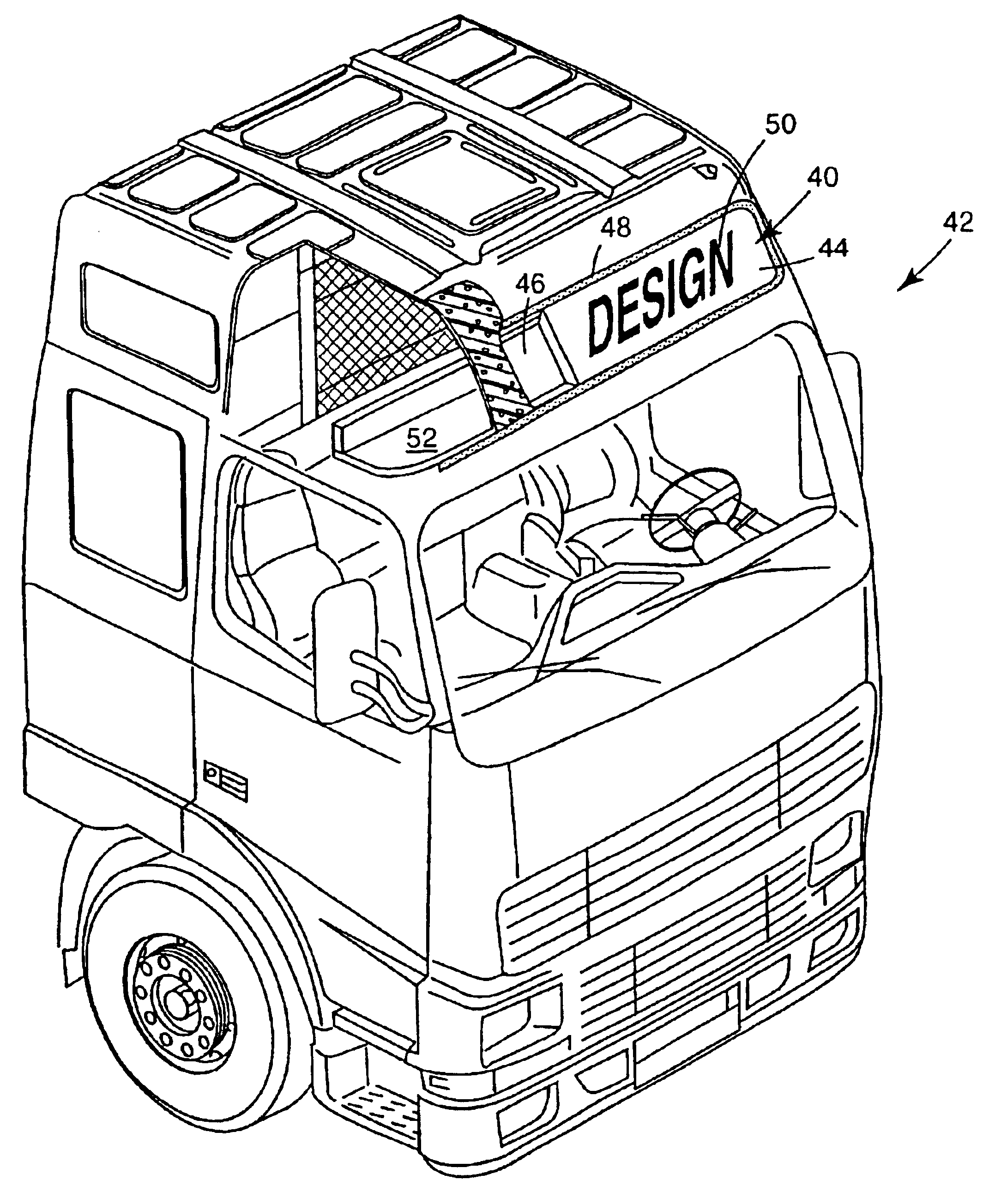
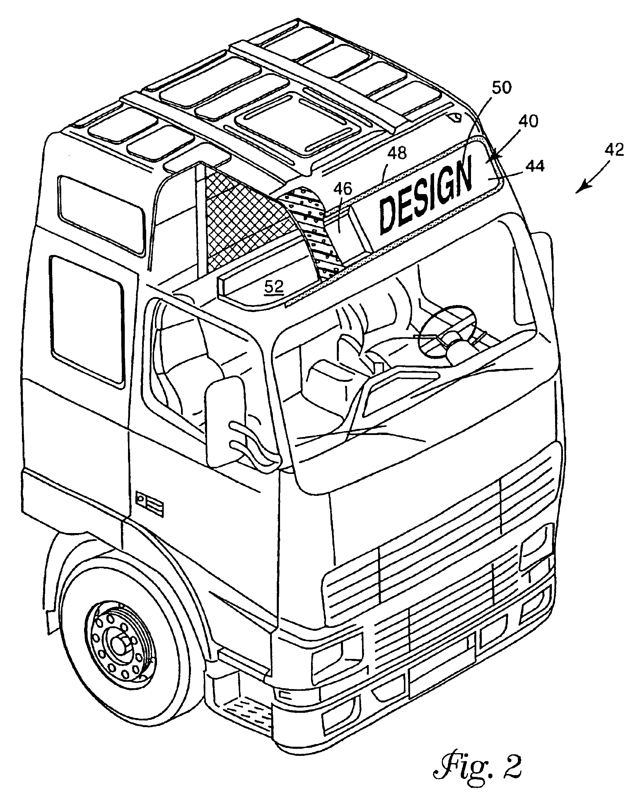
The second prototype sign box was made by Elektrovakuum AS, Ostfold, Norway in Norway and shipped to 3M in St. Paul. The sign box was press formed using standard TiO.sub.2 PMMA with an average diffuse reflectance of approximately 60%. The box was molded to fit the shape of a Volvo H3 model heavy truck glass sign face. Approximate box interior dimensions were 190 cm.times.40 cm.times.4 cm. The pressformed box made by Elektrovakuum was an experimental part, not standard manufacture.

The back and sides of the box interior were lined with TIPS, (the same film described in Example 1). Example 2 was constructed using the same light fiber as used in Example 1. A 2.25 m fiber with vinyl tape white Scotchcal M manufactured by 3M Company, St. Paul Minn. extraction was placed along the lower edge of the back half of the sign box. The extraction stripe was positioned to direct side emitting light upward, across the film lined box surface. A hole was cut on the side of the box near the lower edge...

example 3

Example 3 was constructed using the back half of the sign box described in Example 2. The standard frosted glass of a Volvo H3 model truck sign was used as the sign face and box lid. Again the box was lined with diffuse reflective film. The film used for Example 3 was a TiO.sub.2 loaded vinyl film with an average reflectivity of 95%, product number VS8480 produced by 3M.


PUM


Abstract

A compact, and low maintenance back lit illuminated sign (10), especially such a back lit sign suitable for use on a vehicle. The shallow back lit illuminated sign (10) comprises a housing (12), a light source (30) suitable for supplying light to a light fiber (20), and at least one side-light emitting fiber (20). The housing (12) has a sign face (14) and an interior surface (16, 18) that includes a back surface (19). The sign face (14) has an illuminated area that diffusely transmits light. The back surface (19) is located at a depth from the sign face (14). One or more side-light emitting fibers (20) are connected so as to receive light from the light source (30) and are mounted within the housing (12) so as to limit the amount of emitted light, from the fiber(s) (20), that travels directly to the sign face (14).

Description

FIELD OF INVENTIONThis invention is directed in general to back lit signs that are illuminated using light fiber(s) and that exhibit diffuse reflection of light from the light fiber(s). More particularly, the invention is directed to such a lighted sign that is compact in the thickness dimension (i.e., has a shallow depth) and requires little maintenance. Even more particularly, the invention is directed to such a lighted sign that is suitable for use on a vehicle (e.g., an automobile). The invention is also directed to methods for making and using these signs.BACKGROUND OF INVENTIONLighted signs are everywhere in modern countries. The sign can educate, entertain, inform, or warn the viewer. The sign can be designed for close or distant viewing. Lighting is provided to assure the viewer can see the message, particularly during dimly lit days or nighttime. Lights require energy to power them. Modern countries readily can provide the power, but those who pay for the energy are always ...

Claims


Application Information

Patent Timeline
Patent Type & Authority Patents(United States)
IPC IPC(8): F21V9/00B60Q1/50F21V8/00F21V15/00F21W107/10F21Y101/00G09F13/04
CPCB60Q1/503F21V9/00G02B6/001B60Q1/50G02B6/0001
Inventor OLMAN, CHERYL A.SCHROEDER, KRISTIN M.LOWE, ROBERT H.
Owner 3M INNOVATIVE PROPERTIES CO
Learn More