
Whole body stereotactic localization and immobilization system

a stereotactic and immobilization system technology, applied in the field of medical equipment and methods, can solve the problems of exposing healthy tissue to unwanted radiation, affecting the accuracy so as to reduce diaphragmatic and abdominal movements, improve the effect of immobilization and positioning, and improve the accuracy

Inactive Publication Date: 2004-11-30
MEDICAL INSTR & DIAGNOSTICS
View PDF28 Cites 103 Cited by
  • Summary
  • Abstract
  • Description
  • Claims
  • Application Information

AI Technical Summary

Benefits of technology

are increased accuracy, reliability, and whole body localization. Immobilization is achieved by the use of a vacuum mold system or polyurethane foam mold for posterior (the part of the body nearest the frame base) areas and a thermoplastic body mold to cover large body surfaces in the ventral or anterior plane. The method of combined anterior and posterior form fitting custom molded immobilization, which cover wide surface areas of the body, improves immobilization and repositioning as well as minimizing diaphragmatic and abdominal movements. The vacuum or foam molds and the thermoplastic molds can be stored and reused for each patient in a radiation fractionation or other treatment regimen. All components of the invention, including the visible frame coordinates and scales, provide for precise target treatment.
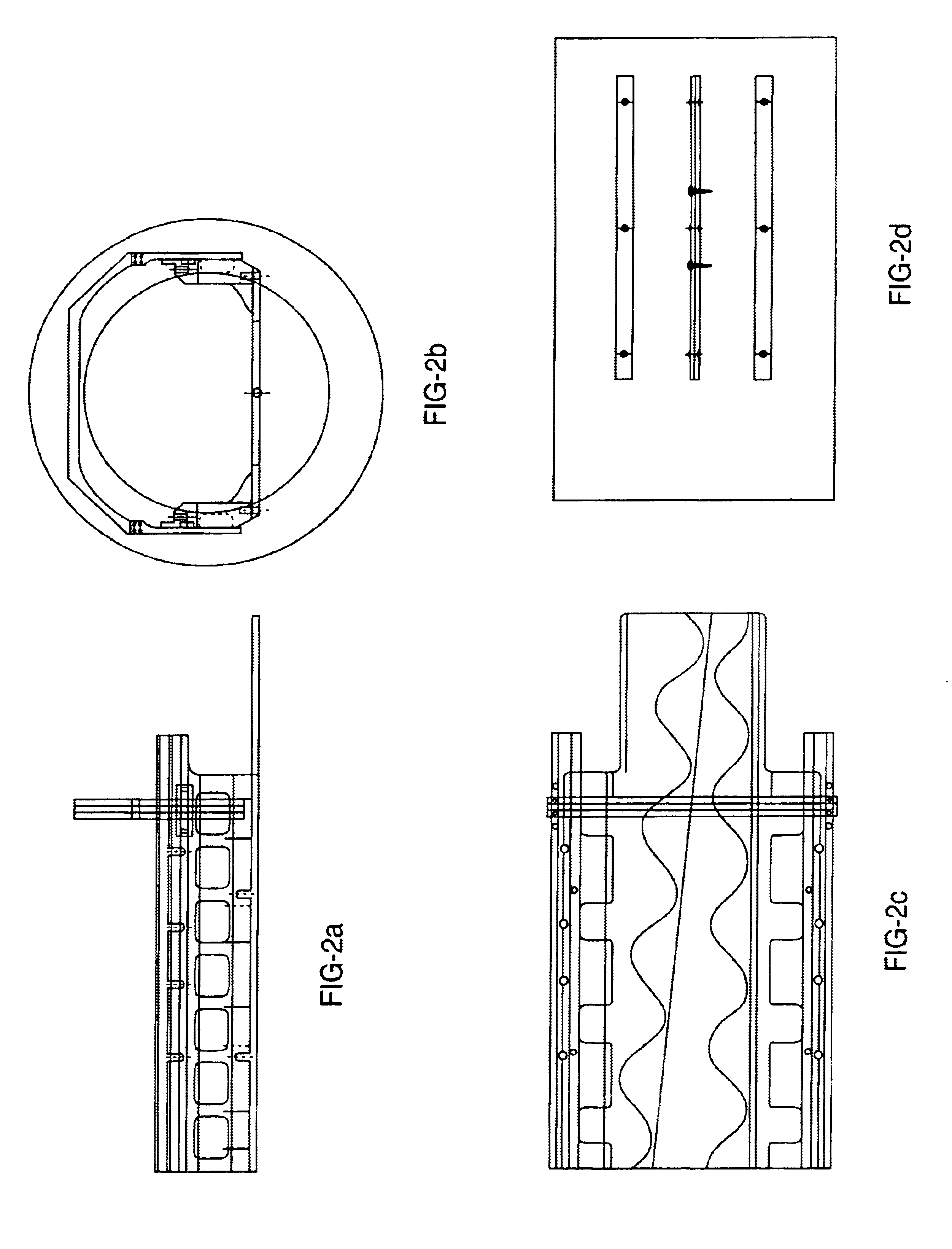
The localization features of most stereotactic frames are similar, differing mainly in the organization of the coordinate system of the frame and its mechanical dimensions. All stereotactic frames are created for the purpose of immobilization, precise patient repositioning, and localization of volume structures or lesions within the volumetric space defined by the frame and the immobilized body part. With regards to stereotactic frames, the general convention is that the long axis of the body (longitudinal axis) is given the designation of the z-axis in the Cartesian coordinate system of three-dimensional spatial localization. The left-right transverse axis is generally designated as the x-axis and the anterior / posterior (vertical) axis is designated as the y-axis. Most conventional stereotactic frames use incremental indicators in millimeters and centimeters along each axis for precise coordinate referencing. The aim of the stereotactic frame system of the present invention is to permit a wide area of body immobilization and allow precise stereotactic imaging and positioning of body areas within the frame.

Problems solved by technology

They also tend to smear and fade.
Patient movement could invalidate target localization and expose healthy tissue to unwanted radiation.

Method used


Image

  • Whole body stereotactic localization and immobilization system
  • Whole body stereotactic localization and immobilization system
  • Whole body stereotactic localization and immobilization system

Examples


Embodiment Construction

)

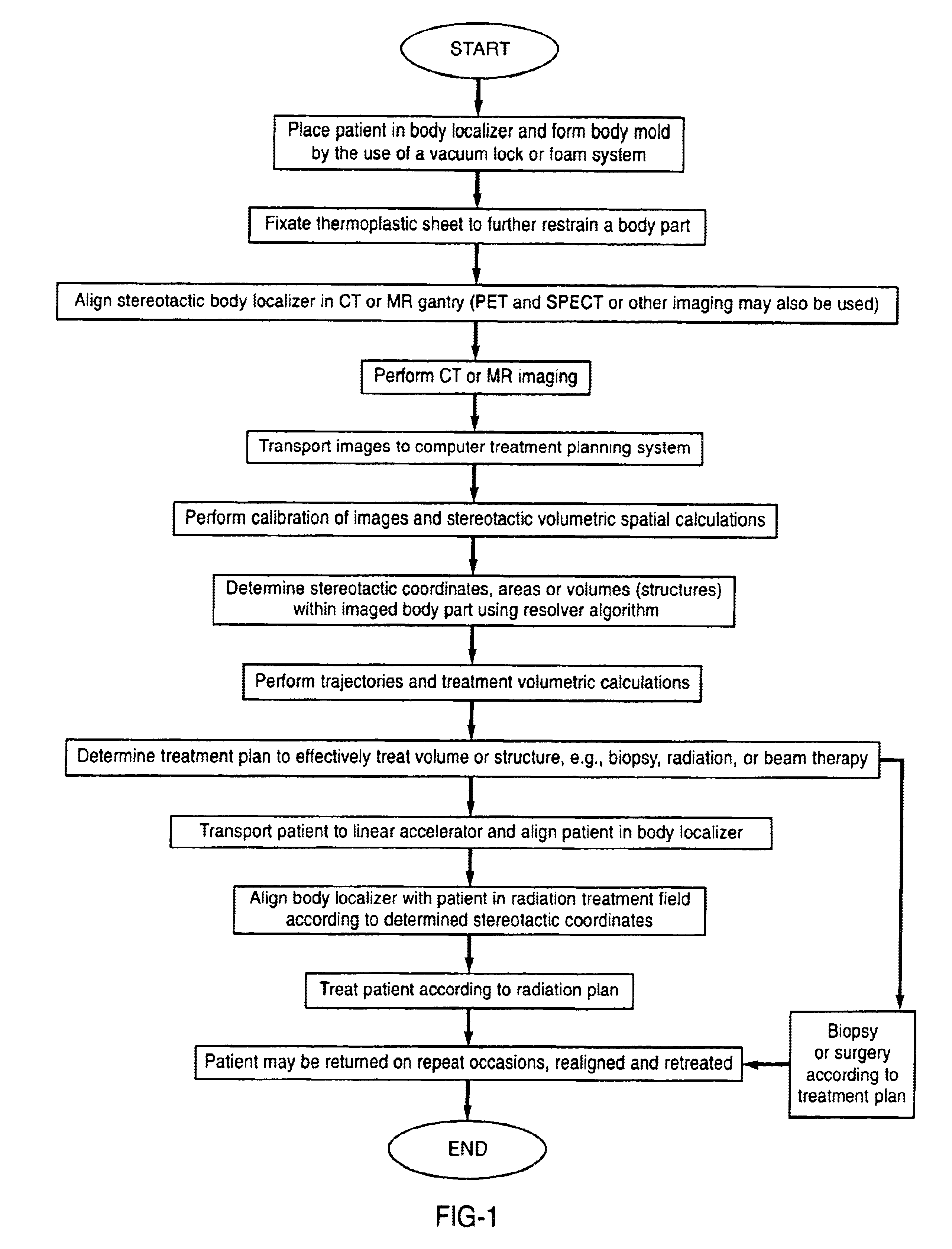
The present invention is a whole body stereotactic localization system with an imaging resolver apparatus and method for stereotactic alignment. More particularly, the present invention relates to a method and apparatus for precisely imaging structures or volumes (target volumes) within a patient's body and realigning the position of target volumes for the purpose of stereotactic treatment planning. Such treatment planning can include biopsies, radioisotope implantation, surgical procedures, radiosurgery / stereotactic radiation therapy, or such other diagnostic or therapeutic measures that may be required by a medical practitioner.

The invention permits aligning and imaging a body part by immobilizing the body part within a stereotactic body localization system having an imaging resolver fiducial localizer for precise imaging and localization of the body parts within the apparatus. The system comprises a frame including a base and sides with an imaging localization fiducial arrangeme...


PUM


Abstract

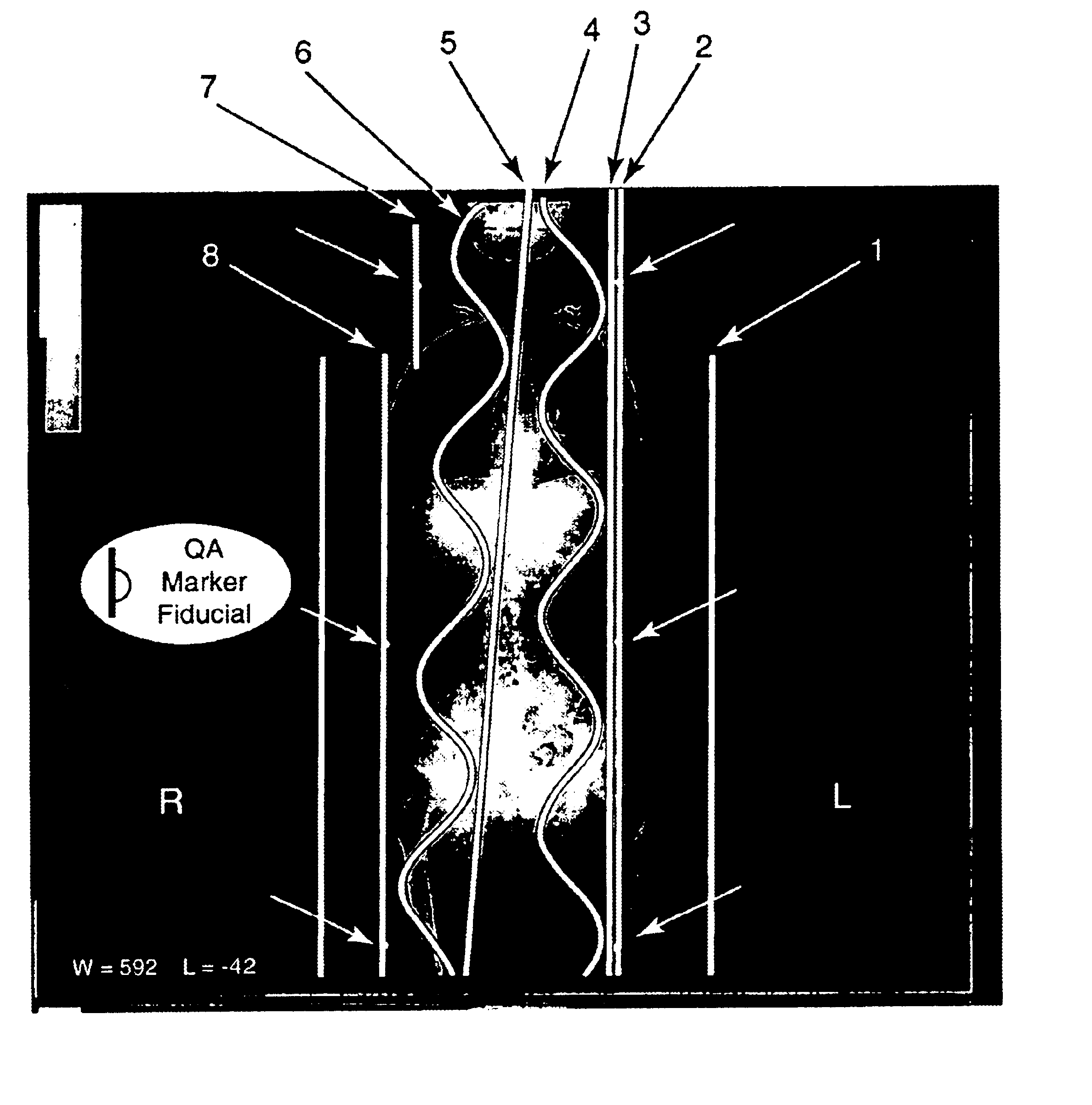
An apparatus and method for aligning and imaging a body part which immobilizes the body part within a stereotactic body localization system having an imaging resolver fiducial localizer for precise imaging and localization of the body parts within the apparatus. Both anterior and posterior immobilization methods can be used. A continuous array of coupled fiducials is employed with at least one pair formed in a pi / 2 horizontal linked sine and cosine wave fiducial pattern.

Description

1. Field of the Invention (Technical Field)The present invention relates to medical equipment and methods, more particularly to equipment and methods for radiation therapy including stereotactic localization and immobilization systems and methods.2. Background ArtFractionated radiation therapy to a target lesion within the body is the primary method used for radiation therapy. This method requires precise immobilization and repositioning of the patient for other treatment sessions. Stereotactic localization and procedures on cranial and extra-cranial body parts have a similar requirement.Note that the following discussion refers to a number of publications by author(s) and year of publication, and that due to recent publication dates certain publications are not to be considered as prior art vis-a-vis the present invention. Discussion of such publications herein is given for more complete background and is not to be construed as an admission that such publications are prior art for ...

Claims


Application Information

Patent Timeline
Patent Type & Authority Patents(United States)
IPC IPC(8): A61B19/00A61B6/04A61B5/055
CPCA61B5/064A61B5/706A61B6/0421A61B6/0492A61B19/54A61B19/203A61B5/055A61N2005/1097A61B2019/207A61B2019/5454A61N5/1049A61B2090/101A61B90/14A61B90/39A61B2090/3954
Inventor HARDY, TYRONE L.DEMING, LAURA R.
Owner MEDICAL INSTR & DIAGNOSTICS
Learn More