

Electro-optic display and lamination adhesive
a technology of optical display and adhesive composition, applied in the direction of optical elements, identification means, instruments, etc., can solve the problems of preventing their widespread use, imposing stringent requirements on the adhesive, and inadequate service life of these displays, so as to achieve economic manufacture of the display
- Summary
- Abstract
- Description
- Claims
- Application Information
AI Technical Summary
Benefits of technology
Problems solved by technology
Method used
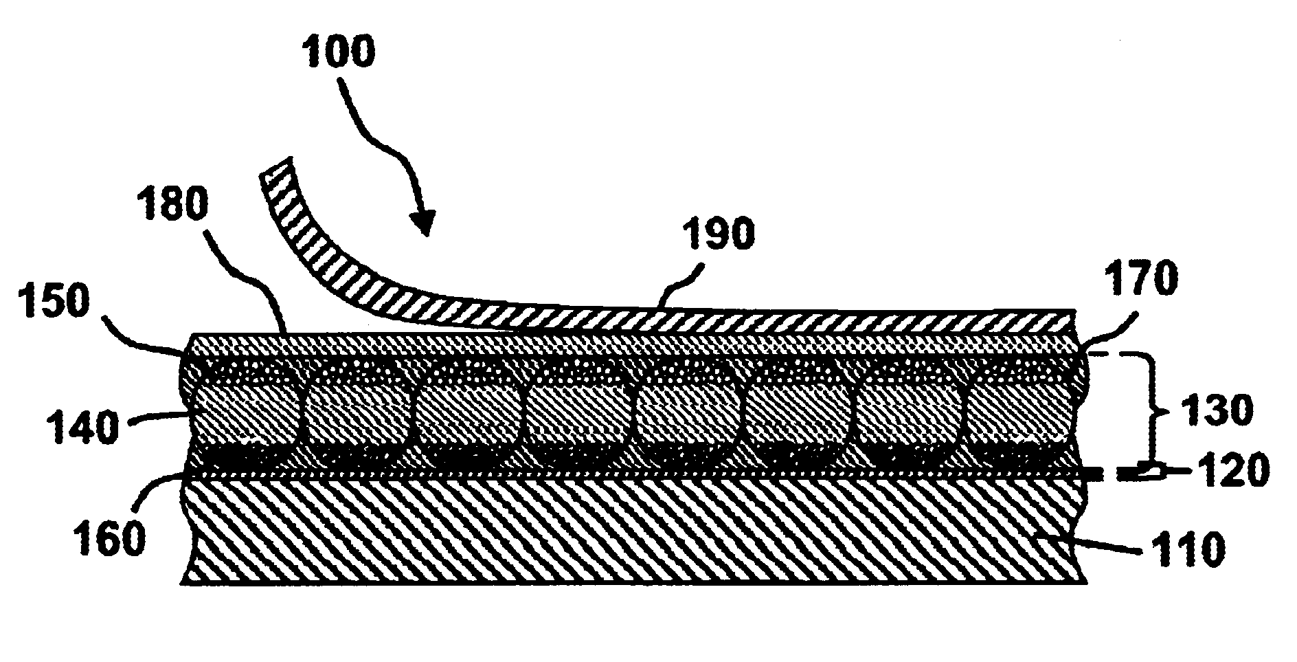
Image

Examples
example 1
except that R 9000 was substituted for U KA 8713, that the storage period was 4000 hours, and that the volume resistivity measurements were supplemented by measurements of the dielectric constant of the blends using the same impedance spectrometer as previously mentioned. The volume resistivity results are shown in FIG. 3 of the accompanying drawings and the dielectric constant results in FIG. 4.
From FIG. 3, it will be seen that, although the volume resistivities of both R 9320 and R 9000 underwent substantial changes over the test period, the blends had much more stable resistivities. In particular, the performance of the 50 / 50 w / w blend was outstanding, displaying a variation by less than a factor of 2 throughout the storage period. FIG. 4 shows that this same 50 / 50 w / w blend displayed essentially no variation in dielectric constant during the test period.
example 3
This Example illustrates the improved stability of the volume resistivity and dielectric constant of the aforementioned R 9320 upon prolonged storage provided by blending the material with the aforementioned U 53. (U 53 is sold as an adhesive but has been found to give insufficient adhesive strength when used in the type of electrophoretic display used in these experiments.)
Example 2 was repeated, except that the aforementioned U 53 was substituted for the R 9000 and that the storage period was 6000 hours. The volume resistivity results are shown in FIG. 5 of the accompanying drawings and the dielectric constant results in FIG. 6.
From FIG. 5, it will be seen that the substantial changes in the volume resistivities of R 9320 over the test period were much less pronounced in the blends. In particular, the resistivities of the 75 / 25 and 50 / 50 w / w blends were within the acceptable range throughout the storage period. Similarly, FIG. 6 shows that both the 75 / 25 and 50 / 50 w / w blends displ...
example 4
This Example illustrates the improved stability of the volume resistivity and dielectric constant of the aforementioned R 9320 upon prolonged storage provided by blending the material with the aforementioned U 54. (U 54 is sold as an adhesive but has been found to give insufficient adhesive strength when used in the type of electrophoretic display used in these experiments.)
Example 2 was repeated, except that the aforementioned U 54 was substituted for the R 9000 and that the storage period was 5500 hours. The volume resistivity results are shown in FIG. 7 of the accompanying drawings and the dielectric constant results in FIG. 8.
From FIG. 7, it will be seen that the substantial changes in the volume resistivities of R 9320 over the test period were much less pronounced in the blends. In particular, the resistivities of the 75 / 25 and 50 / 50 w / w blends were within the acceptable range throughout the storage period. Similarly, FIG. 8 shows that both the 75 / 25 and 50 / 50 w / w blends displ...
PUM
| Property | Measurement | Unit |
|---|---|---|
| enthalpy | aaaaa | aaaaa |
| dielectric constant | aaaaa | aaaaa |
| temperature | aaaaa | aaaaa |
Abstract
Description
Claims
Application Information