Cylinder bank work output balancing based on exhaust gas A/F ratio

a technology of exhaust gas and work output, applied in the direction of electric control, machines/engines, mechanical equipment, etc., can solve the imbalance of a/f ratio, insufficient bank-to-bank cam position balancing, and inability to ensure the balancing of intake air flow. achieve the effect of maintaining the equivalency of the first and second a/f ratio

Inactive Publication Date: 2005-01-04
GM GLOBAL TECH OPERATIONS LLC
View PDF6 Cites 21 Cited by
  • Summary
  • Abstract
  • Description
  • Claims
  • Application Information

AI Technical Summary

Benefits of technology

Accordingly, the present invention provides a system for balancing first and second work outputs between first and second cylinder banks of an engine. The system includes a first intake camshaft associated with the first cylinder bank and a first fuel injector associated with the first cylinder bank. A controller trims pulse-width of the first fuel injector until first and second A / F ratios of respective exhaust of the first and second cylinder banks are equivalent. The controller adjusts timing of the first intake camshaft to effect air flow into the first cylinder bank and trims the pulse-width to maintain equivalency of the first and second A / F ratios.

Problems solved by technology

Balancing of the bank-to-bank cam positions, however, does not insure bank-to-bank balancing of intake air flow.
This is a result of manufacturing and assembly variations that create ambiguity between sensed cam positions and actual timing of intake valves.
Imbalance of intake air flow results in an A / F ratio imbalance across the cylinder banks that effects engine smoothness and engine efficiency.
However, this compensation strategy fails to correct the fundamental problem of air flow imbalance.
This, however, results in increased manufacturing and assembly costs.

Method used


Image

  • Cylinder bank work output balancing based on exhaust gas A/F ratio
  • Cylinder bank work output balancing based on exhaust gas A/F ratio
  • Cylinder bank work output balancing based on exhaust gas A/F ratio

Examples


Embodiment Construction

The following description of the preferred embodiments is merely exemplary in nature and is in no way intended to limit the invention, its application, or uses.

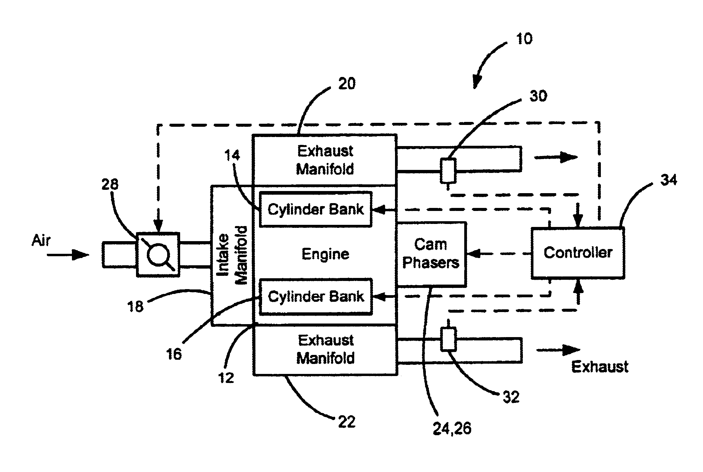
Referring now to FIG. 1, a vehicle 10 is shown and includes an engine 12 having cylinder banks 14,16, an intake manifold 18, exhaust manifolds 20,22 and cam phasers 24,26. Air is drawn into the intake manifold 18 through a throttle 28 and is distributed to the cylinder banks 14,16. Exhaust gas from the cylinder banks 14,16 flows through the respective exhaust manifolds 20,22 to an exhaust system. Oxygen (O2) sensors 30,32 are associated with each exhaust manifold 20,22. The O2 sensors 30,32 measure the amount of O2 in exhaust gas exiting the respective exhaust manifolds 20,22.

A controller 34 balances the cylinder banks 14,16 of the engine 12. The controller 34 communicates with the throttle 28, the cylinder banks 14,16, the cam phasers 24,26 and the O2 sensors 30,32. As discussed in further detail below, the controller 34 rec...


PUM


Abstract

A system for balancing first and second work outputs between first and second cylinder banks of an engine includes a first intake camshaft associated the first cylinder bank and a first fuel injector associated with the first cylinder bank. A controller trims a pulse-width of the first fuel injector until first and second A/F ratios of respective exhaust of the first and second cylinder banks are equivalent. The controller adjusts timing of the first intake camshaft to effect air flow into the first cylinder bank and trims the pulse-width to maintain equivalency of the first and second A/F ratios.

Description

FIELD OF THE INVENTIONThe present invention relates to engine control, and more particularly to balancing work output of cylinder banks of the engine based on an exhaust gas air-to-fuel (A / F) ratio.BACKGROUND OF THE INVENTIONConventional internal combustion engines having a V-, W-or flat (i.e., horizontally opposed) shaped configurations include multiple cylinder banks. The cylinder banks include pistons that are reciprocally driven through cylinders by a combustion process to produce driving force. An air and fuel mixture is provided and is ignited within the cylinders during the combustion process. The air and fuel quantity within a cylinder defines the work output of the cylinder. The air rates of the cylinders are controlled by the phase angle or timing of a camshaft with respect to a driven crankshaft. The fuel rate is controlled by the pulse-width of a fuel injector.The timing of intake valve closing with respect to piston position within the cylinder influences the volume of ...

Claims


Application Information

Patent Timeline
Patent Type & Authority Patents(United States)
IPC IPC(8): F02D41/00F02D41/14F02D41/40F02D41/34
CPCF02D41/0002F02D41/0082F02D41/0085F02D41/401F02D41/1443Y02T10/42F02D2041/001Y02T10/44Y02T10/40
Inventor HERRIN, RONALD J.
Owner GM GLOBAL TECH OPERATIONS LLC
Why Eureka
Try Eureka