
Flow control device and method of controlling flow

Inactive Publication Date: 2005-01-04
ORBITAL RES
View PDF12 Cites 79 Cited by
  • Summary
  • Abstract
  • Description
  • Claims
  • Application Information

AI Technical Summary

Benefits of technology

The present invention relates to a flow control device and more particularly to modular flow control device with

Problems solved by technology

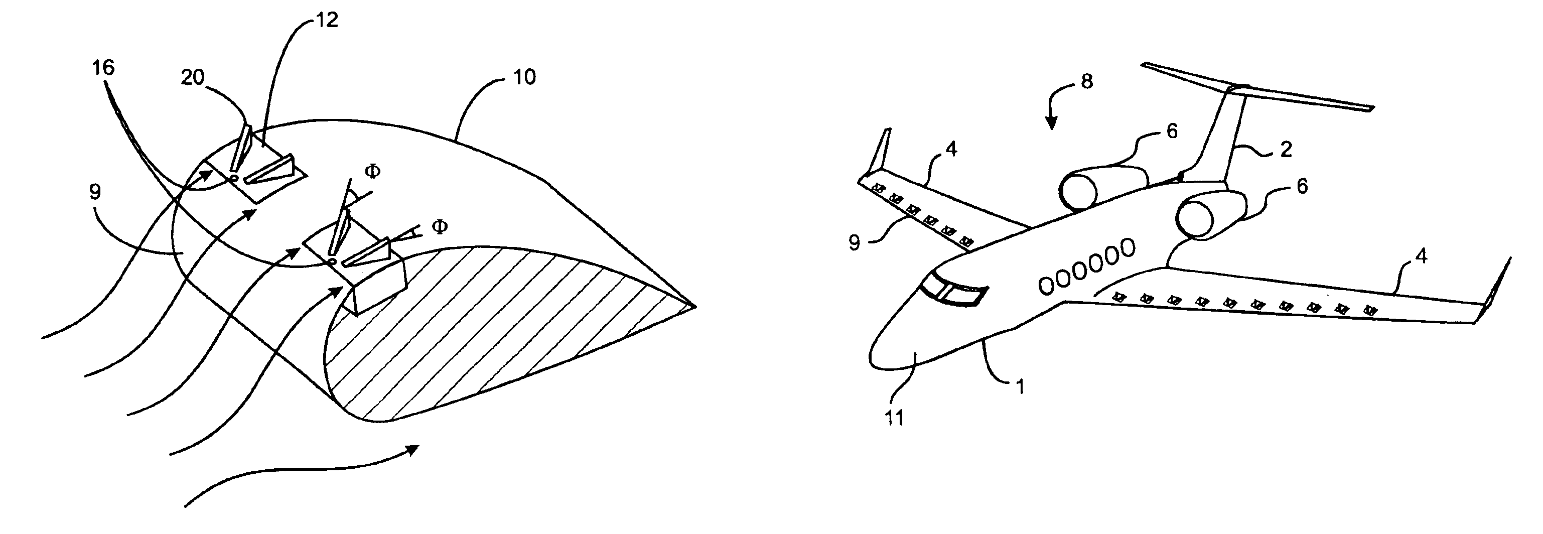
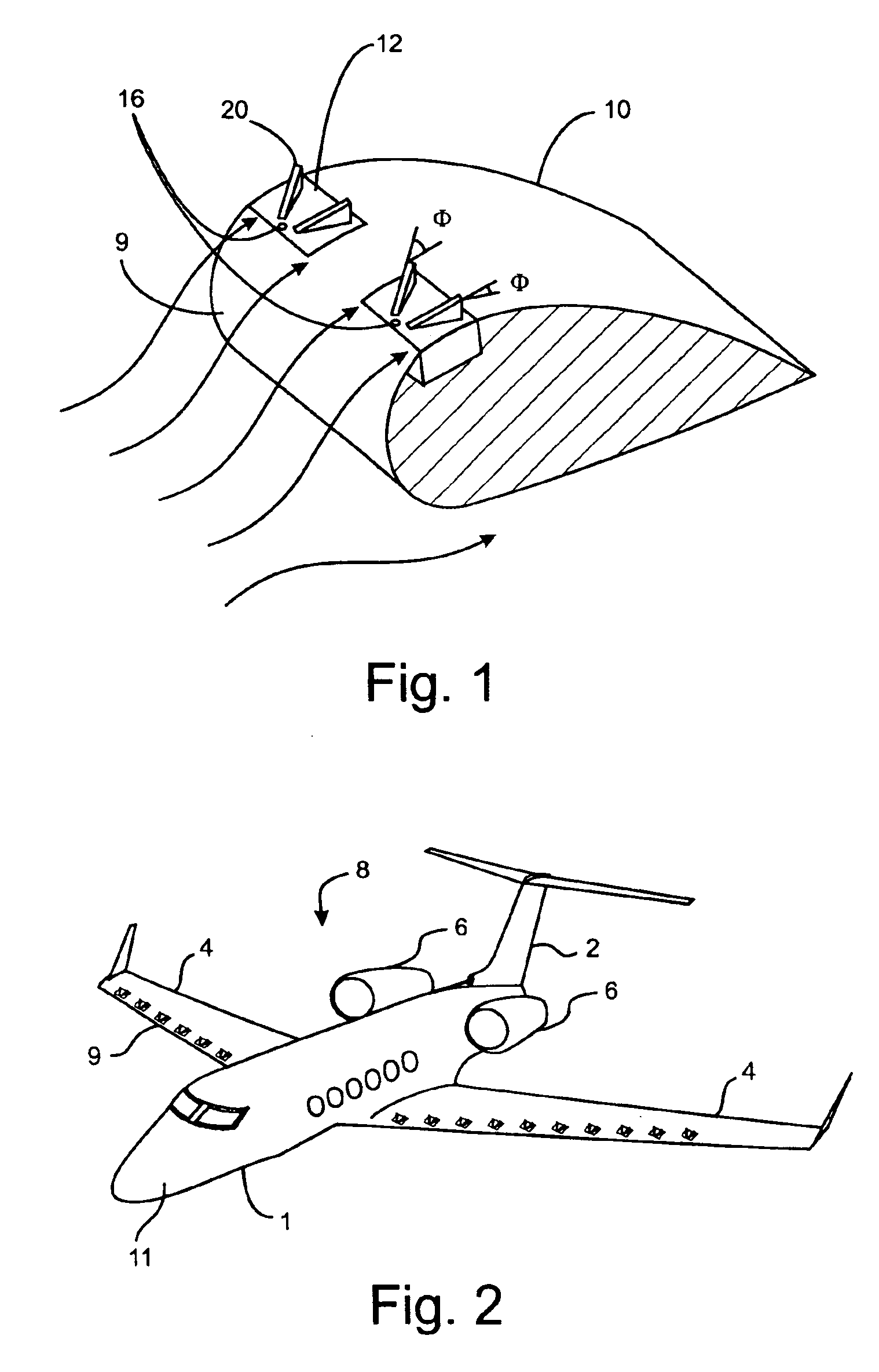
In the case of a wing, if separation is too near the leading edge, the wing stalls and the aircraft looses lift and the pilot looses control.
With a high angle of attack, such as during a steep ascent at takeoff, or a steep descent at landing, there is a tendency of the air flow passing across the upper surface of the wing to become destabilized and separate from the wing.
This separation of fluid flow leads to disastrous results because the suction peak on the upper surface of the wing is diminished, and the lift is dramatically reduced while the drag is substantially increased.
Passive devices, which involve the presence of a device continually protruding from the flow surface even with no boundary layer flow separation, such as when cruising at a given elevation, leads to increased drag on the flow surface resulting in increased fuel consumption and reduced efficiency of the air vehicle.
In addition, with military aircraft the protruding passive flow control devices produce a radar signature compromising the stealth capability of the aircraft.
Most of these active devices operate in an open-loop mode and are slow and relatively unresponsive.
Also, while active devices such as mechanical vortex generators can be responsive they also have some limitations.
With these systems, the vacuum or pressure required to generate a vortex to reattach the flow is fairly high at high speeds, which increases the power requirements, weight and the cost of the system.
Complications and significant expense can occur with these systems if the lengthy pneumatic systems develop a leak or if the system is activated at a high frequency.
Additionally, the openings in the surface of the wing or airfoil may lead to drag and unwanted surface effects.
These requirements and complications make such systems bulky, complicated, heavy and expensive.
These are their being relatively slow in response, and high in weight.
The method disclosed in Palmer cannot determine the incipience of a stagnation point or separation point at any location on the flow surface.

Method used


Image

  • Flow control device and method of controlling flow
  • Flow control device and method of controlling flow
  • Flow control device and method of controlling flow

Examples


second embodiment

a method to identify the shift in measured power spectrum of the signal from the pressure transducer to identify stall utilizes a recursively identified system model, particularly an Auto-Regressive Moving Average (ARMA) model. An example of this type of model is used in Orbital Research Inc's patented predictive adaptive controller referenced herein. The ARMA recursive identification method attempts to fit specific models to the measured pressure data. Evaluation of this data reveals distinct, identifiable model order shifts based upon attached and separated airflow over the airfoil, which can be used to set the deployment of the flow effectors for the control of fluid flow. Further analysis of the frequency spectrum of the data reveals recognizable oscillations in the pressure distribution over the airfoil. This clear characterization alongside the model order shifts allows the ORICA identifier to classify discrete models based upon each flow condition, thus allowing precise contr...

third embodiment

a method for quantifying the power spectrum measured by the pressure transducer is by using Short-Time Fourier Transforms (STFT). A Discrete Fourier transform (DFT), and its numerically efficient complement the Fast Fourier Transform (FFT), both provide frequency information of a digitized signal, such as the pressure measurement recorded by the pressure transducer on the surface of the airfoil. The DFT and FFT both assume that the signal that is being measured is stationary in time. However, in the case of the airfoil and other typical aerodynamic models, the measured pressure signal is not stationary in time, which means a typical DFT / FFT approach is inapplicable. However, for short time periods the signal maybe considered to be stationary. Therefore, it is possible to estimate the mean power spectrum by segmenting the pressure data into epochs lasting anywhere from 0.1-5 seconds each, and then applying a discrete-time Fourier transform (DFT) to the windowed data. The DFT is used ...


PUM


Abstract

The present invention relates to a flow control device and more particularly to reactive modular flow control device with deployable flow effectors. The present invention further relates to a method of operating the flow control device. One embodiment of the present invention includes a method of controlling air flow across a surface of an aircraft under certain flight conditions comprising the steps of sensing fluid separation from the surface by measuring the pressure on the surface; determining a standard deviation of the pressure measurements over a period of time; and deploying a flow of effector in response to the standard deviation of the pressure measurements exceeding a predetermined threshold number.

Description

BACKGROUND OF THE INVENTION1. Field of the InventionThe present invention relates to a flow control device and more particularly to modular flow control device with deployable flow effectors. The present invention further relates to a method of operating the flow control device.2. Technical BackgroundIn numerous aeronautical and hydrodynamic applications it is desirable to control the flow of fluid across a surface. As fluid flows over a flow surface, like air over an airplane wing or forebody, air over turbine engine blades, or water around the hull of a ship or a submarine, it forms a fluid boundary layer at the surface. The fluid boundary layer is a thin layer of viscous flow exhibiting certain pressure variations that affects the operation of the vehicle surface. The pressure variations within the fluid flow inside the boundary layer directly affect the performance, including the maneuverability and stability, of the vehicle. The oscillation of the pressure variation within the ...

Claims


Application Information

Patent Timeline
IPC IPC(8): B64C23/00B64C23/06
CPCB64C23/06Y02T50/162B64C3/58Y02T50/10
Inventor LISY, FREDERICK J.MODARRESZADAH, MOHAMMEDPATEL, MEHUL P.DICOCCO, JACK M.CARVER, REEDSCHMIDT, ROBERT N.PRINCE, TROY
Owner ORBITAL RES
Learn More