Light wavelength converting system

a technology of light wavelength and conversion system, which is applied in the field of light wavelength conversion system, can solve the problems of adversely affecting the oscillation strength of semiconductor lasers, unstable oscillation strength, and non-perfect reflectance of the ar coating, so as to prevent the variation of the oscillating wavelength and maintain the linearity of the il characteristic

Inactive Publication Date: 2005-01-04
FUJIFILM HLDG CORP +1
View PDF19 Cites 31 Cited by
  • Summary
  • Abstract
  • Description
  • Claims
  • Application Information

AI Technical Summary

Benefits of technology

In the light wavelength converting module, since the resonator length of the external resonator is made larger than the coherent length of the fundamental wave, the interference due to the fed-back light to the semiconductor laser can be prevented so that the linearity of the IL characteristic can be maintained. Namely, if the resonator length of the external resonator is made larger than the coherent length of the semiconductor laser, when the resonator length of the external resonator changes somewhat, it does not greatly affect the oscillating wavelength of the semiconductor laser. Accordingly, by merely hermetically sealing a small number of the components including the semiconductor laser and the light wavelength converting element, this light wavelength converting module can output a converted wavelength wave stably and can sufficiently respond to changes in humidity or atmospheric pressure of the environment in which the light wavelength converting module is used.
In the above-described light wavelength converting unit and the light wavelength converting module, since the semiconductor laser is driven by the current on which high frequency current has been superposed, vertical mode competition of the semiconductor laser is suppressed to thereby prevent variation of the oscillating wavelength, thus making the light output of the converted wavelength wave stable.

Problems solved by technology

However, such an AR coating does not exhibit a perfect reflectance of 0%.
Accordingly, the fundamental wavelength is reflected slightly at an emitting end of the light wavelength converting element and then returns to the semiconductor laser, thus adversely affecting oscillation of the semiconductor laser.
When the amount of light which returns to the semiconductor is great, a vertical mode hop occurs or the oscillation strength becomes unstable.
In a semiconductor laser having such a characteristic as that illustrated in FIG. 9, a problem arises in that, when an APC (automatic power control) or an output stabilizing control is applied to the semiconductor laser, the variation in the amount of light over time becomes large, namely, the noise increases.
When such a light wavelength converting module is used as a recording light source for a laser scanner, for example, the problem arises that more noise is generated in the recorded image.
In particular, since the semiconductor laser whose oscillating wavelength has been locked by the above-described external resonator has high monochromaticity, it is easy for the above-described interference to occur, and the problem due to the fed-back light is likely to be caused.
Therefore, in this light wavelength converting element, there arises the problem that the converted wavelength wave emitted from the other end surface of the optical waveguide is reflected largely, thus making it difficult to align optical axis of the laser beam with other optical elements.
In a case in which the proximal end surface is inclined as described above, a problem arises in that the light emitted from the semiconductor laser does not efficiently enter the light wavelength converting element.
However, in the conventional wavelength stabilized laser having the aforementioned structure, there is a problem in that the linearity of the IL characteristic is unsatisfactory.
In this way, the rays of light having different optical paths interfere with each other.
Thus, when the oscillating wavelength changes, since the above-described state in which the rays of light interfere with each other also changes, the linearity of the IL characteristic may deteriorate.
Accordingly, there has been the drawback in that rapid modulation cannot be performed with an excitation solid-state laser.
Further, in order to structure the internal resonator, reflection films or AR films, which correspond to an incident wavelength, a resonating wavelength, and an emitting wavelength, respectively, must be provided at the solid-state laser crystalline or the member which forms the resonator, and the manufacturing of the internal resonator becomes complicated.
Moreover, due to the use of the laser diode in the transverse multi-mode, a transverse mode hop is caused which causes noise.
However, a problem arises in that, due to changes in the humidity or atmospheric pressure in the environment in which the laser is used, the length of the resonator changes, and an oscillating wavelength thereby varies.
However, in this excitation solid-state laser, there has been a problem that since all of the main structural components must be hermetically sealed, the device becomes bulky and the manufacturing cost thereof becomes high.
Further, there has been a problem in that, when the number of components to be hermetically sealed is large, a mirror or the like deteriorates over time due to gasses which are generated from the respective components so that the output from the solid-state laser thereby deteriorates.

Method used


Image

  • Light wavelength converting system
  • Light wavelength converting system
  • Light wavelength converting system

Examples


first embodiment

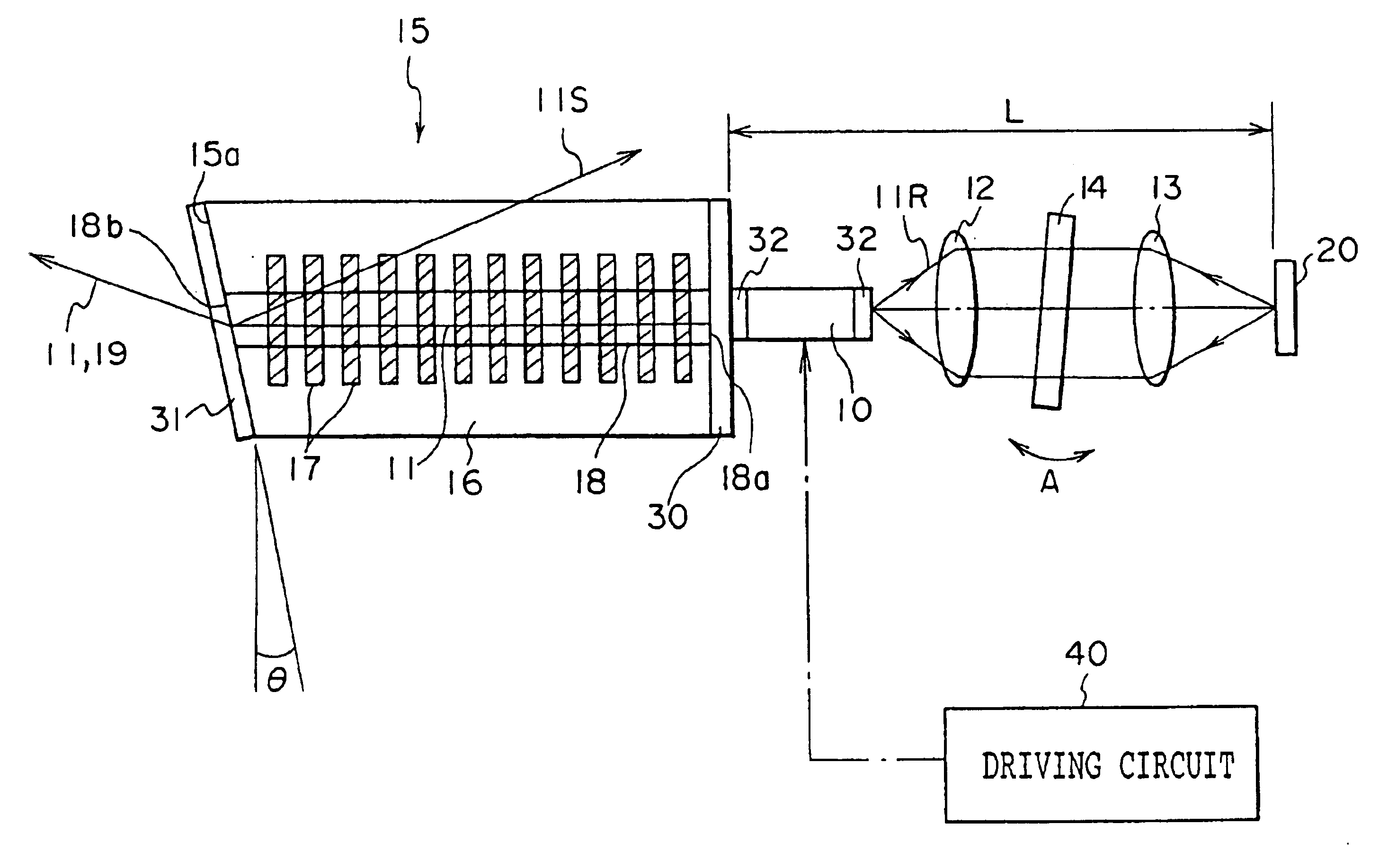
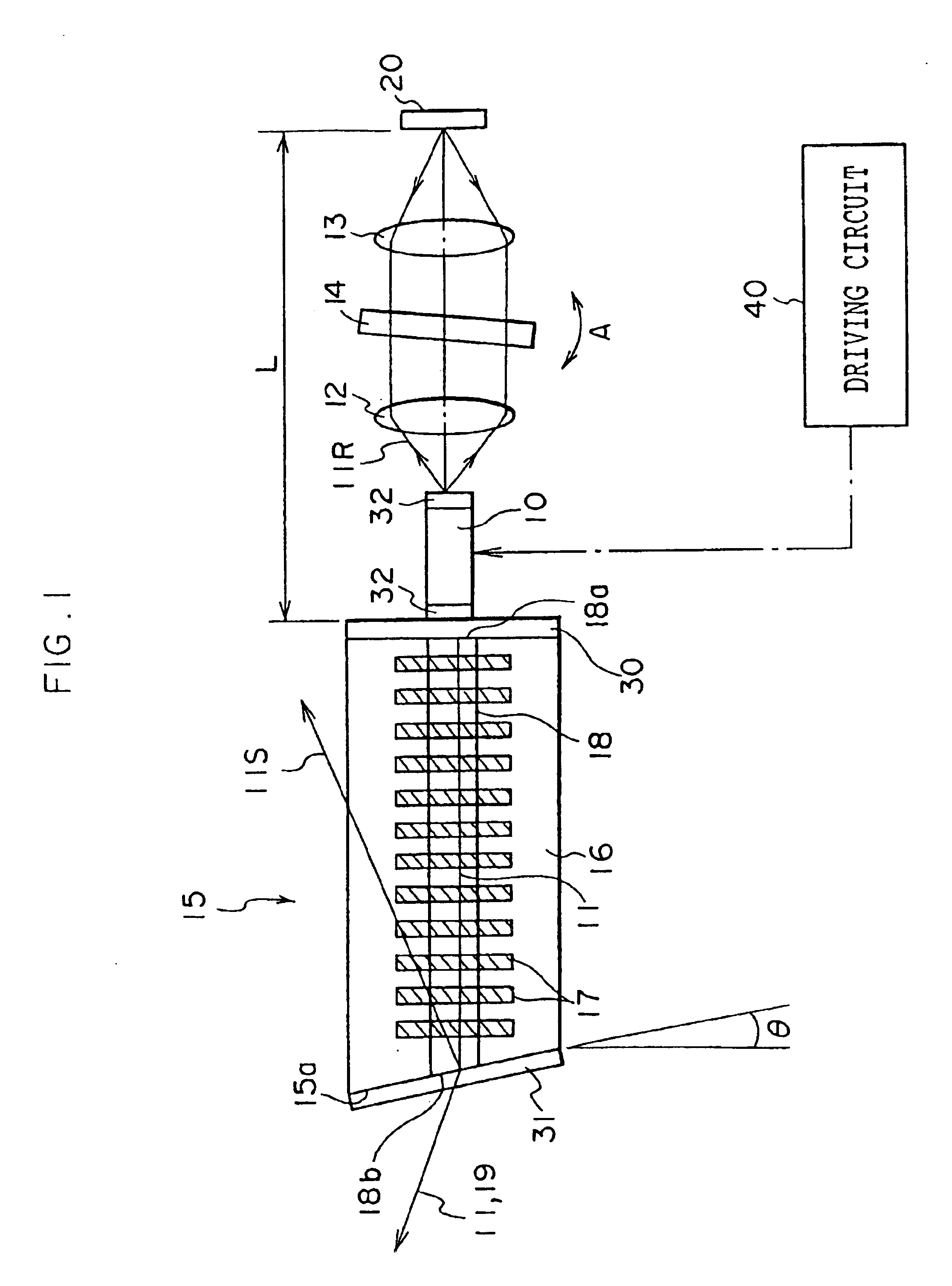
FIG. 1 shows a light wavelength converting module according to a first embodiment of the present invention. As shown in this figure, this light wavelength converting module comprises a semiconductor laser 10, a collimator lens 12 which makes parallel a laser beam 11R (i.e., a backward emitting light) which is emitted in a state of a divergent light from this semiconductor laser 10, a condenser lens 13 which converges the laser beam 11R which has been made parallel, a narrow band-pass filter 14, as a wavelength selecting element, which is disposed between the collimator lens 12 and the condenser lens 13, and a mirror 20 which is disposed at a position at which the laser beam 11R is converged by the condenser lens 13.

A forward end surface of the semiconductor laser 10 (a left end surface thereof in FIG. 1) is connected directly to an end surface of a waveguide-type light wavelength converting element 15. The semiconductor laser 10 is driven by a semiconductor laser driving circuit 40 ...

second embodiment

Next, with reference to FIG. 10, a light wavelength converting module according to a second embodiment of the present invention will be explained. Further, in FIG. 10, components identical to those of FIG. 1 are denoted by the same reference numerals, and a description thereof will be omitted (the same may be said of a third embodiment).

In the second embodiment of the present invention, the AR coating 31 is applied to the element end surface 15a including the optical waveguide end surface 18a of the light wavelength converting element 15 such that the AR coating 31 is applied to an external end surface 140a of an MgO-LN crystal block 140 which is made from the same material as the substrate 16 and which has the same refractive index as the effective refractive index of the channel optical waveguide 18, namely, the end surface at the opposite side of the optical waveguide 18.

In the above-described structure, the laser beam 11 (the fundamental wave) which enters, in a state of the div...

third embodiment

With reference to FIG. 11, a light wavelength converting module according to a third embodiment of the present invention will be explained.

In the third embodiment of the present invention, a phase modulation portion 50 is formed between a wavelength converting portion (a portion on which the domain inverting portions 17 are formed) and the end surface 18b of the channel optical waveguide 18 of the light wavelength converting element 15 so that a phase of the laser beam 11 which waves-guides the optical waveguide 18 is modulated. This phase modulation portion 50 is formed by a pair of electrodes 51 and 52 which are disposed at both sides of the channel optical waveguide 18, and an alternating power source 53 which applies an alternating voltage between the pair of the electrodes 51 and 52.

A condition of a proton exchanging process and an annealing process for forming this channel optical waveguide 18 is basically the same as that in the first embodiment of the present invention and c...


PUM

PropertyMeasurementUnit
angleaaaaaaaaaa
angleaaaaaaaaaa
reflectanceaaaaaaaaaa

Abstract

A light wavelength converting element which can reduce an amount of light fed-back to a semiconductor laser. The light wavelength converting element converts a wavelength of a fundamental wave which enters from a first end surface side of an optical waveguide to thereby emit a converted wavelength wave from a second end surface side thereof. The second end surface is inclined with respect to the side surface of the optical waveguide. Also provided is a wavelength stabilized laser having a semiconductor laser, a device which feeds a laser beam emitted from the semiconductor laser back to the semiconductor laser, and a band-pass filter. An optical length between the semiconductor laser and the device is made to be longer than a coherent length of the semiconductor laser, thus improving linearity of a current vs. light output characteristic. Further, a light wavelength converting unit and a light wavelength converting module are provided in which, since an LD-SHG unit formed by a semiconductor laser and a light wavelength converting element is hermetically sealed in a package, the LD-SHG unit can be manufactured easily and has excellent stability over time.

Description

BACKGROUND OF THE INVENTION1. Field of the InventionThe present invention relates to a light wavelength converting system which includes a light wavelength converting element, a light wavelength converting module, and a wavelength stabilized laser.A first aspect of the present invention relates to a light wavelength converting element, and more specifically to an optical waveguide-type light wavelength converting element in which an optical waveguide is formed on a substrate having a nonlinear optical effect.Further, the present invention relates to a light wavelength converting module in which such a light wavelength converting element as described above and an external resonator-type semiconductor laser which makes a laser beam as a fundamental wave enter the light wavelength converting element are connected to each other.A second aspect of the present invention relates to a wavelength stabilized laser in which a semiconductor laser beam is passed through a band-pass filter to the...

Claims


Application Information

Patent Timeline
Patent Type & Authority Patents(United States)
IPC IPC(8): G02F1/377G02F1/35H01S5/14H01S5/00H01S5/022G02F1/37H01S5/068
CPCG02F1/3544G02F1/377G02F1/3775H01S5/141G02F2001/3505G02F2001/3509H01S3/1062H01S5/0092H01S5/02248H01S5/02284H01S5/02438G02F2001/3548G02F1/3505G02F1/3509G02F1/3548H01S5/02251H01S5/02325
Inventor SONODA, SHINICHIROMIURA, HIDEOHATORI, MASAMI
Owner FUJIFILM HLDG CORP
Why Eureka
Try Eureka