

Hydrodynamic coupling
- Summary
- Abstract
- Description
- Claims
- Application Information
AI Technical Summary
Benefits of technology
Problems solved by technology
Method used
Image

Examples
Embodiment Construction
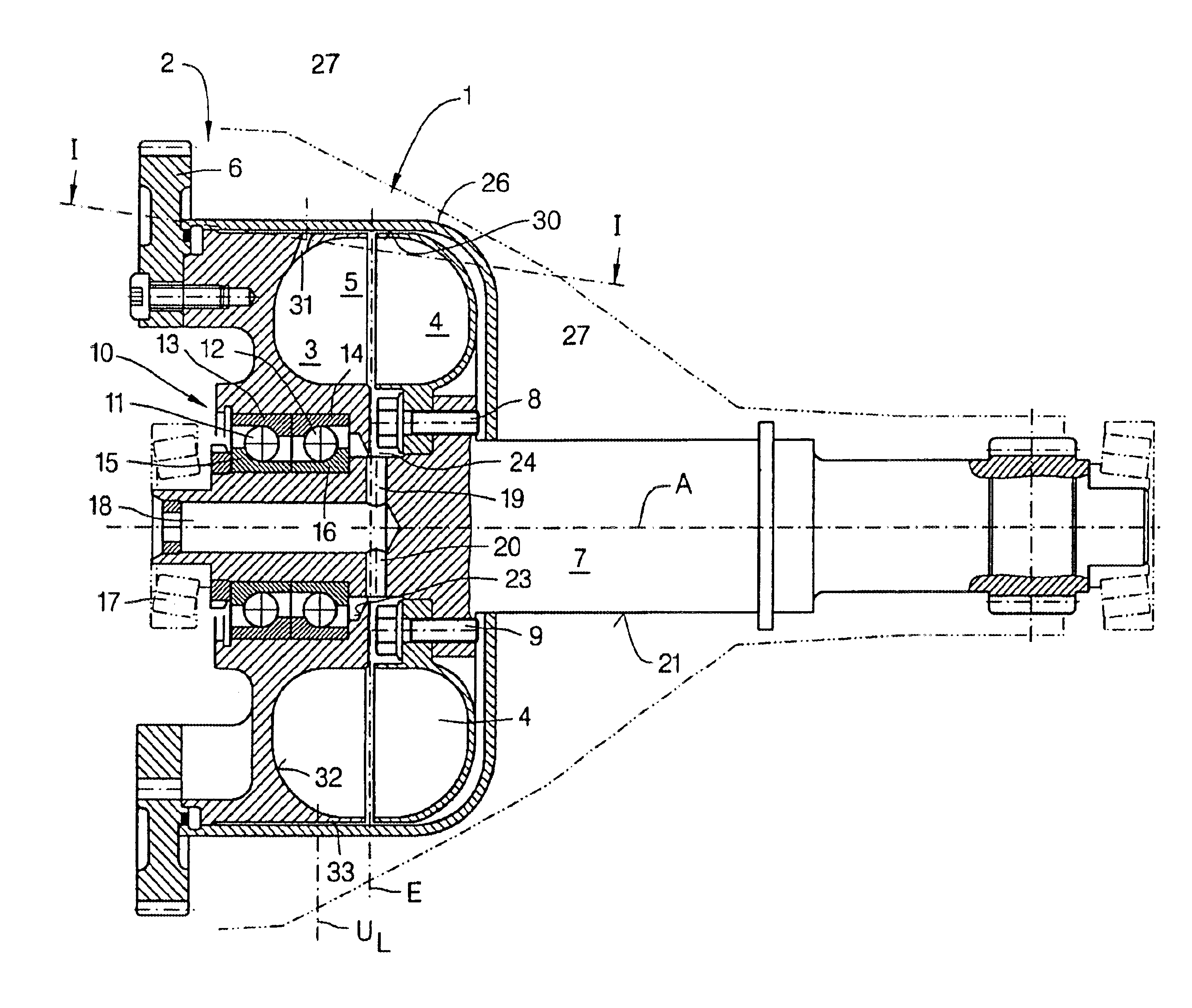
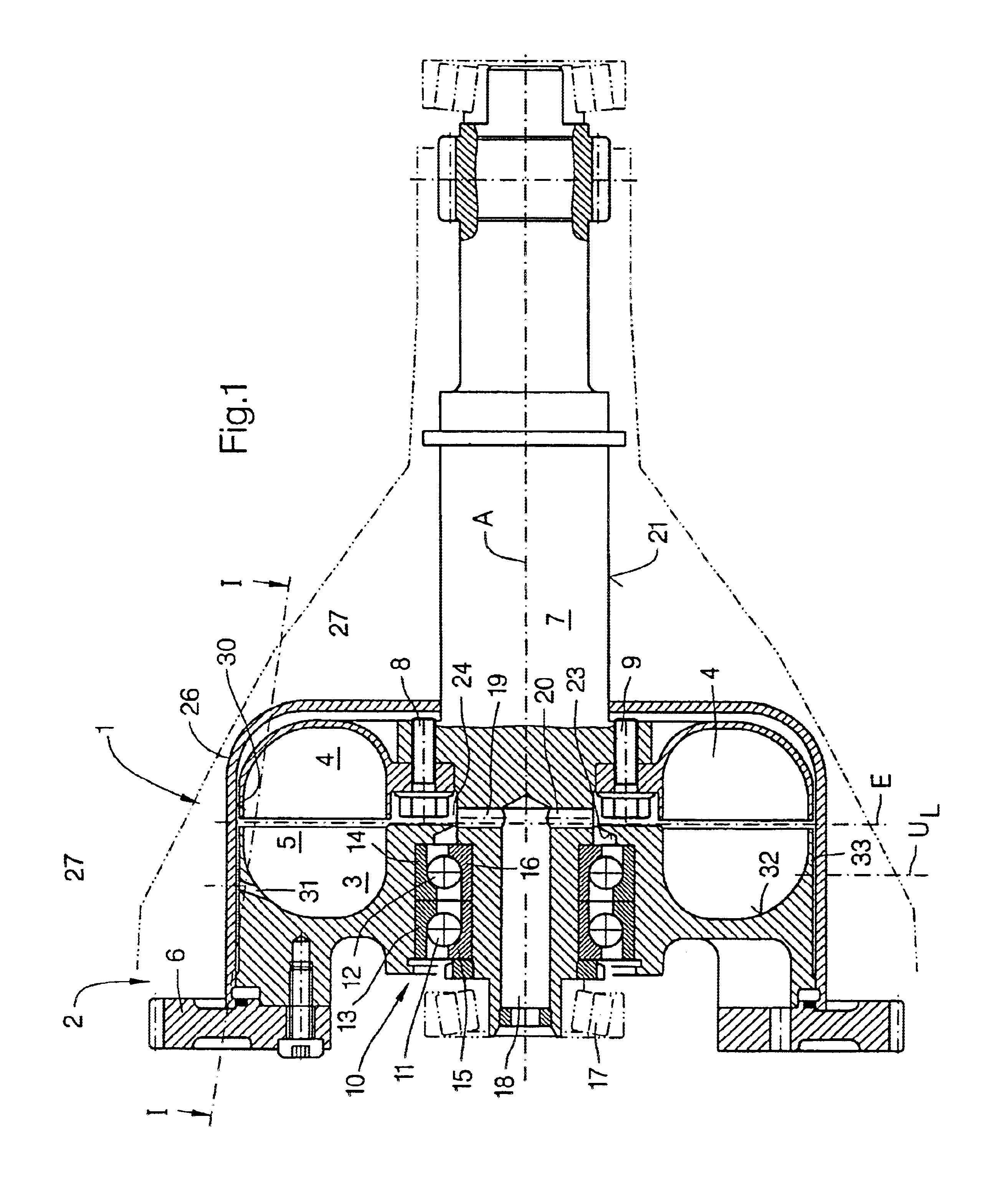
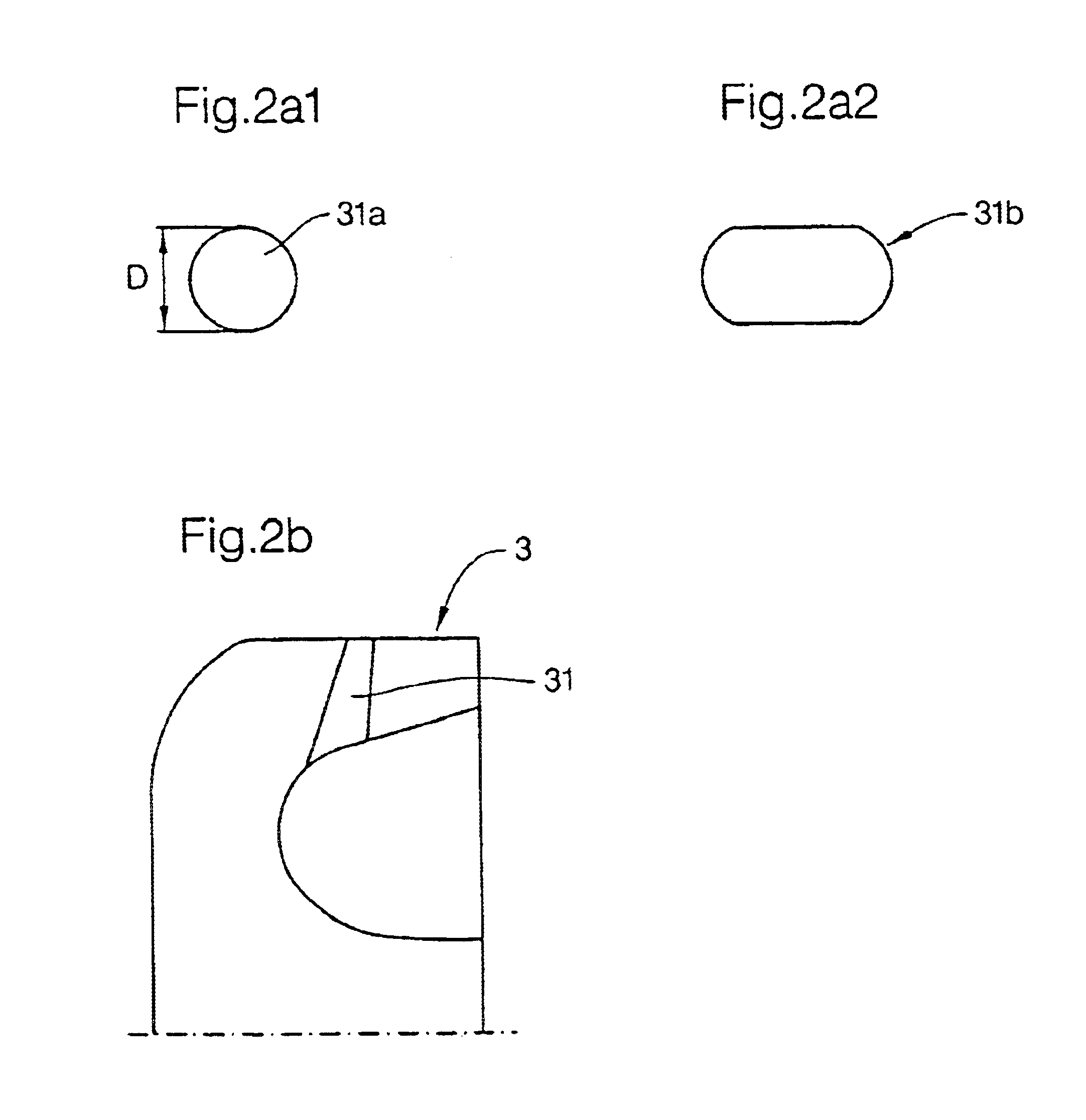
FIG. 1 shows, using the embodiment example in the form of a hydrodynamic coupling 1 in a turbo compound system 2, the solution according to the invention. The hydrodynamic coupling 1 includes a primary wheel 3, which is also characterized as a pump wheel, and a secondary wheel 4, which is characterized as a turbine wheel. Pump and turbine wheel 3 or 4 together form at least one toroidal operating space 5, which can be filled with an operating fluid, for example, with oil. The pump wheel 3 is driven by a gear arranged on a shaft, not shown here, of a drive turbine, not shown here. For this purpose, the gear meshes with a gear 6 coupled so that it is rotationally fixed to the pump wheel 3.
The turbine wheel 4 is arranged on a drive shaft 7 of the hydrodynamic coupling 1. In the embodiment example shown, the turbine wheel 4 is coupled to the drive shaft 7 so that it is rotationally fixed using non-positive and / or positive connections in the form of screw connections, here represented by...
PUM
 Abstract
Description
Claims
Application Information