
Patient monitoring system employing array of force sensors on a bedsheet or similar substrate

Inactive Publication Date: 2005-01-11
TRUSTEES OF BOSTON UNIV
View PDF32 Cites 165 Cited by
  • Summary
  • Abstract
  • Description
  • Claims
  • Application Information

AI Technical Summary

Benefits of technology

In accordance with the present invention, a sensor-based patient monitoring system is disclosed incorporating features that overcome limitations of the prior art. In addition to having superior performance for traditional uses, such as reducing the incidence of patient falls, the system can be used for a variety of other clinical purposes to assist medical personnel and enhance the quality of care.
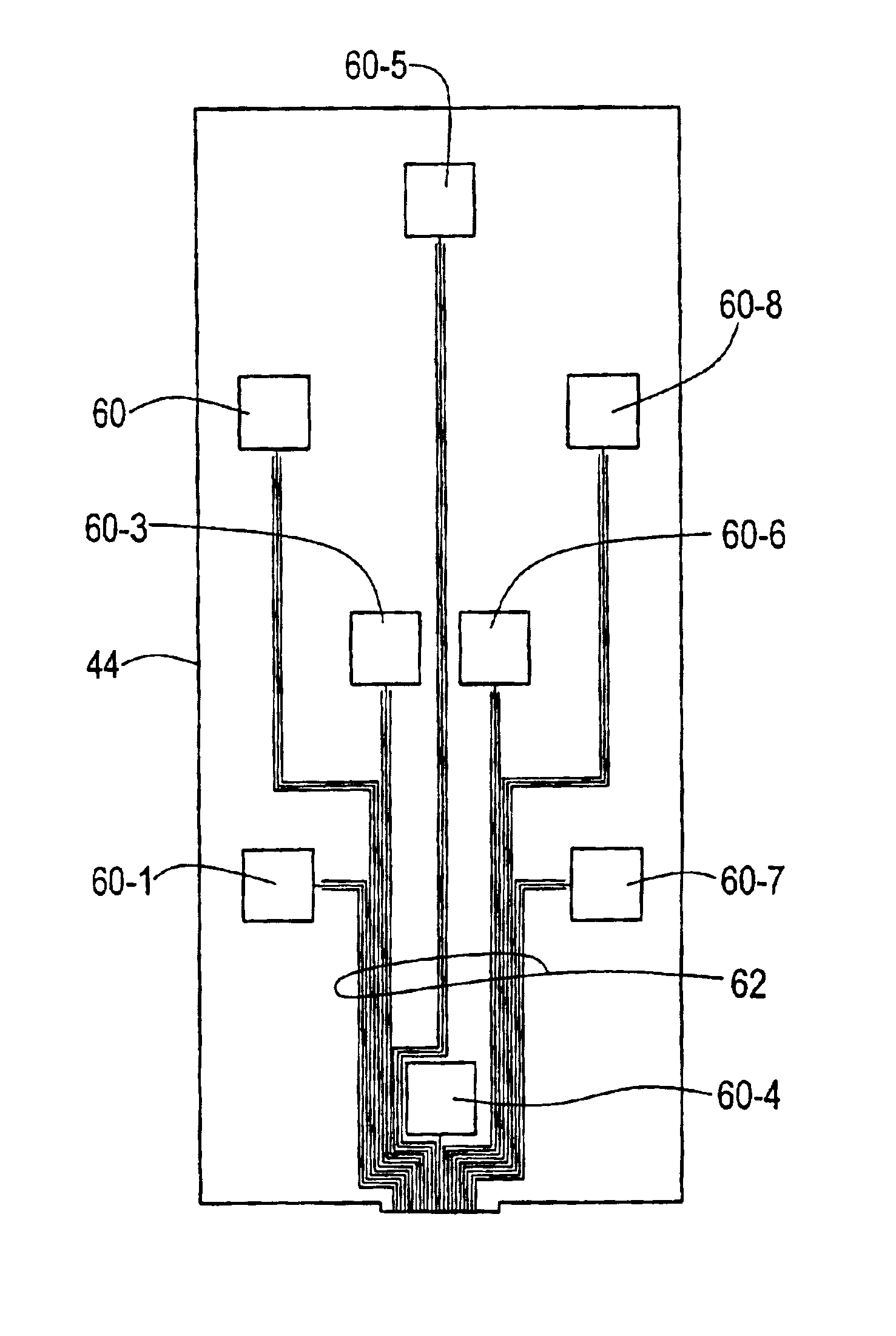
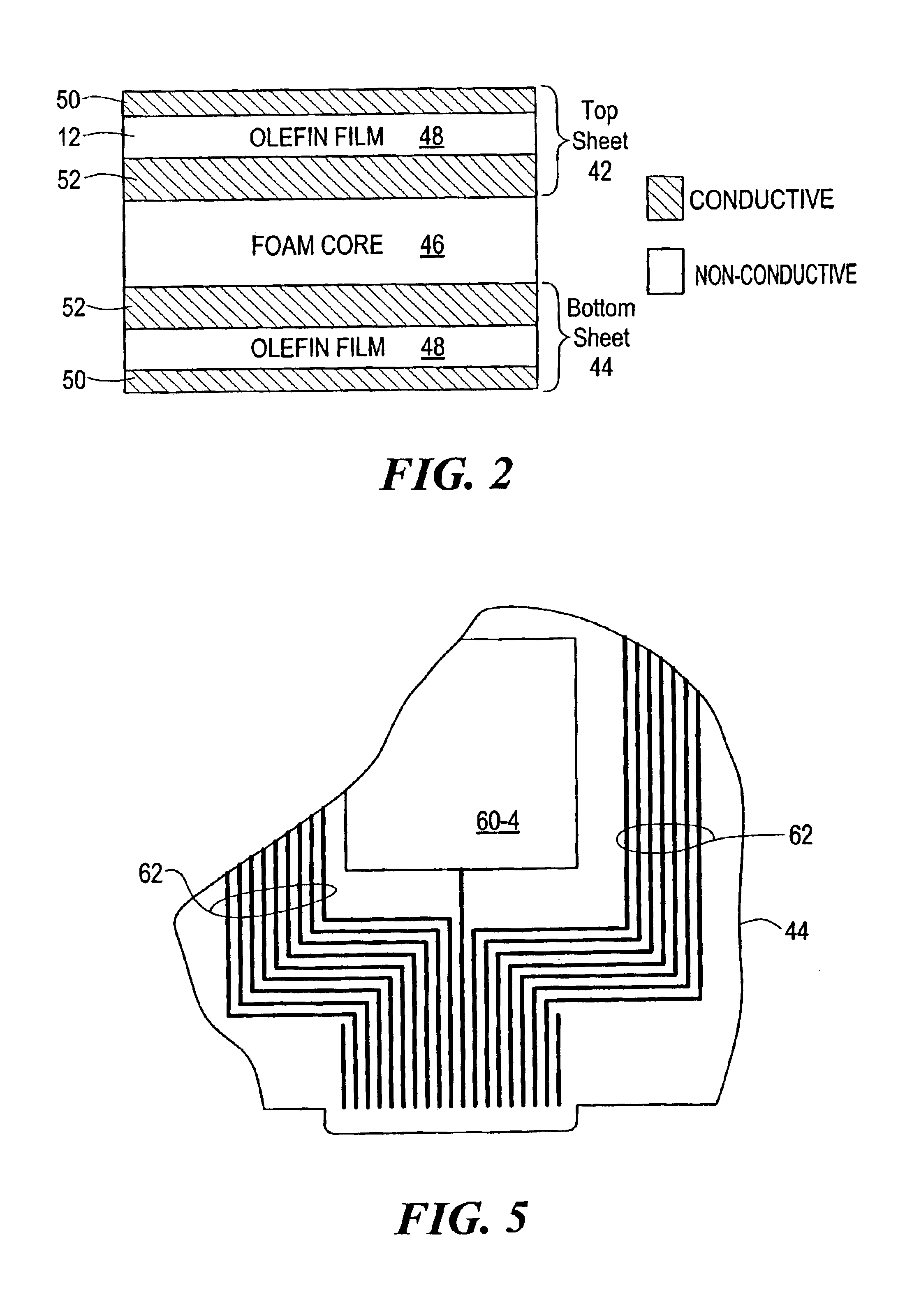
The disclosed laminar sensor is made of layers of olefin film having patterns of conductive ink deposited thereon to form capacitive sensing elements, ground planes, and signal traces. The layers are laminated with a foam core selected to provide desired sensitivity of the capacitive sensing elements for a range of expected patient weights. Both a low-cost process and a high-volume process for manufacturing the sensor are shown.

Problems solved by technology

In many settings, such as hospital wards and nursing homes, there can be problems associated with patients' getting out of bed without supervision or assistance.
Older patients are at risk of breaking their hips in a fall, requiring extended bed rest and attendant problems.
Prior patient monitoring systems have used sensors having certain drawbacks that limit performance.
One such drawback is size.
However, a patient may move into a position away from the sensor, resulting in a false alarm.
Due to the lack of resolution, only limited information can be obtained from the sensor.

Method used


Image

  • Patient monitoring system employing array of force sensors on a bedsheet or similar substrate
  • Patient monitoring system employing array of force sensors on a bedsheet or similar substrate
  • Patient monitoring system employing array of force sensors on a bedsheet or similar substrate

Examples


Embodiment Construction

The disclosure of U.S. patent application Ser. No. 09 / 169,759, filed Oct. 9, 1998 and entitled Center Of Weight Sensor, is hereby incorporated by reference herein.

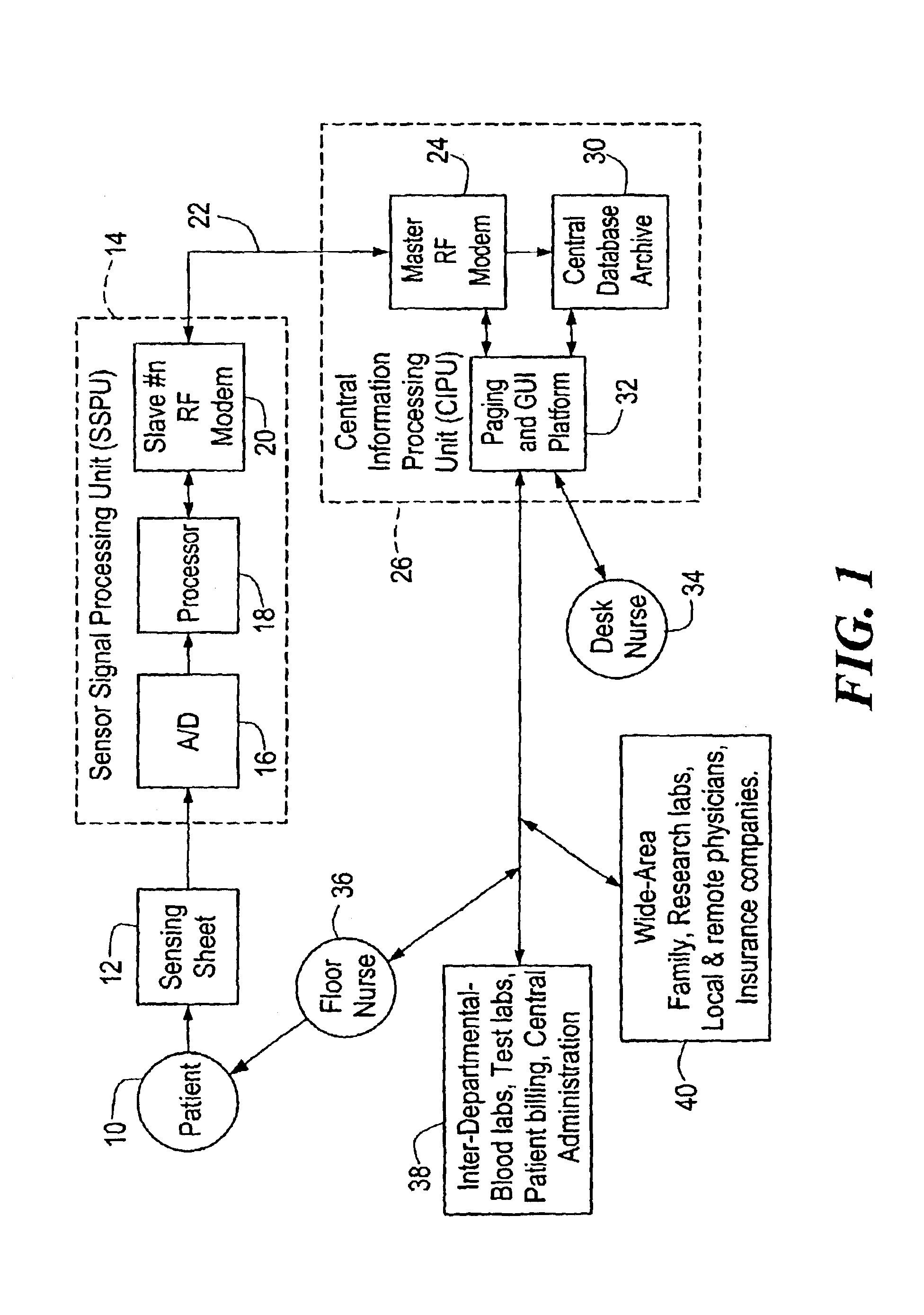
In FIG. 1, the motion of a patient 10 is transmitted to a sensing sheet 12 by direct physical contact, such as exists when the sensing sheet 12 is placed on a bed and the patient 10 lies on top of the sensing sheet 12. The sensing sheet 12 includes a number of spaced-apart sensing elements or transducers (not shown in FIG. 1) capable of converting applied forces into an electrical signals representative of the forces. One example of such a sensing sheet 12, described in detail below, employs sensing elements that function as variable capacitors whose capacitance changes in response to applied forces. Other types of sensing elements may also be employed, such as piezoelectric sensing elements, force-sensing resistors, etc.

The signals generated by the sensing sheet 12 are communicated to a nearby sensor signal processing uni...


PUM


Abstract

A patient monitoring system includes a replaceable laminar sensor to be placed on a bed, the sensor including distributed force sensing elements providing output signals to processing apparatus including a near-bed processor and a central processor coupled to the near-bed processor by a wireless communication link. The processing apparatus applies spatial weighting to the sensor output signals to derive the force distribution across the sensor, and processes the force distribution over time to generate patient status information such as patient presence, position, agitation, seizure activity, respiration, and security. This information can be displayed at a central monitoring station, provided to a paging system to alert attending medical personnel, and used to update medical databases. The sensor may be manufactured from layers of olefin film and conductive ink to form capacitive sensing elements.

Description

STATEMENT REGARDING FEDERALLY SPONSORED RESEARCH OR DEVELOPMENTNot ApplicableBACKGROUND OF THE INVENTIONThe present invention is related to the field of patient monitoring equipment.Patient monitoring systems are used in many settings to assist medical personnel in providing care. In many settings, such as hospital wards and nursing homes, there can be problems associated with patients' getting out of bed without supervision or assistance. A patient may suffer a fall whose effects can range from minor to major. Older patients are at risk of breaking their hips in a fall, requiring extended bed rest and attendant problems. Systems have been known that monitor whether a patient is present in a bed or wheelchair. Essentially, these systems employ a flat sensor laid on the mattress or cushion, and electronic apparatus that responds to signals from the sensor. For example, the strength of a sensor output signal may be proportional to the weight applied to the sensor. The electronic appar...

Claims


Application Information

Patent Timeline
IPC IPC(8): A61B5/11B60N2/00B60R21/01G01G19/414G01G19/00G01G19/44G01G19/40G01L1/20G06K9/00A43B3/00B60R21/015
CPCA43B3/00B60R21/01526A61B5/11A61B5/1115A61B5/112A61B5/1126A61B5/6892B60N2/002G01G19/4142G01G19/44G01G19/445G01G23/3728G01L1/205G06K9/00348G06K9/00362B60R21/01516A43B3/0005A61B2562/0252A61B2562/046A43B3/34G06V40/25G06V40/10
Inventor HUBBARD, JR., JAMES E.
Owner TRUSTEES OF BOSTON UNIV
Learn More