Wireless downwhole measurement and control for optimizing gas lift well and field performance

a technology of gas lift well and measurement and control, applied in the field of petroleum well, can solve the problems of determining production cost, affecting the performance of gas lift well, and only being able to approximate optimization,

Inactive Publication Date: 2005-01-11
SHELL OIL CO
View PDF130 Cites 62 Cited by
  • Summary
  • Abstract
  • Description
  • Claims
  • Application Information

AI Technical Summary

Problems solved by technology

The ongoing supply of compressed lift gas is a major determinant of production cost.
Optimizing the lift gas injection rate to minimize production cost is thus of direct value, but generally this optimization can only be approximated since the relationship between injection rate and production rate cannot be monitored in real time, and since there is only an indirect relationship between annulus pressure, determined by lift gas injection rate, and the resulting volumetric gas flow rate at the gas lift valve.
Consequently there is significant delay between changing the flow of lift gas at the surface, and the corresponding change in annulus pressure which determines the injection rate at the gas lift valve downhole.
Surface measurements of fluid flow rates and composition also exhibit delays which may be of the order of hours, the transit time for fluids from the production zones to the wellhead.
Gas lift exhibits an instability termed “heading” if the gas flow rate is lowered below a certain threshold in attempts to either conserve lift gas, or reduce production rate.
This increase in bottom-hole pressure reduces the pressure differential across the gas-lift valve, further reducing the lift gas injection rate and therefore further reducing the withdrawal rate of fluids from the formation.
The consequence is cyclic “heading” or surging which eventually leads to cessation of all fluid flow and the death of the well.
An important issue with heading is that the long latency between changes in bottom hole conditions and their consequences as visible production rate fluctuations at the surface makes recovery from heading difficult once it has been initiated.
Intermittent gas lift is considered undesirable for a number of reasons.
The intermittent demand for a high flow of lift gas is hard on compressors, which operate best against a steady demand.
To mitigate this factor accumulators may be used to store gas awaiting the next lift cycle, but these are a capital cost item with ongoing maintenance, and at best a partial solution.
The high intermittent flow requires oversize piping between the compressor station and the dependent wells, and the cyclic load on the piping is mechanically stressful.

Method used


Image

  • Wireless downwhole measurement and control for optimizing gas lift well and field performance
  • Wireless downwhole measurement and control for optimizing gas lift well and field performance
  • Wireless downwhole measurement and control for optimizing gas lift well and field performance

Examples


Embodiment Construction

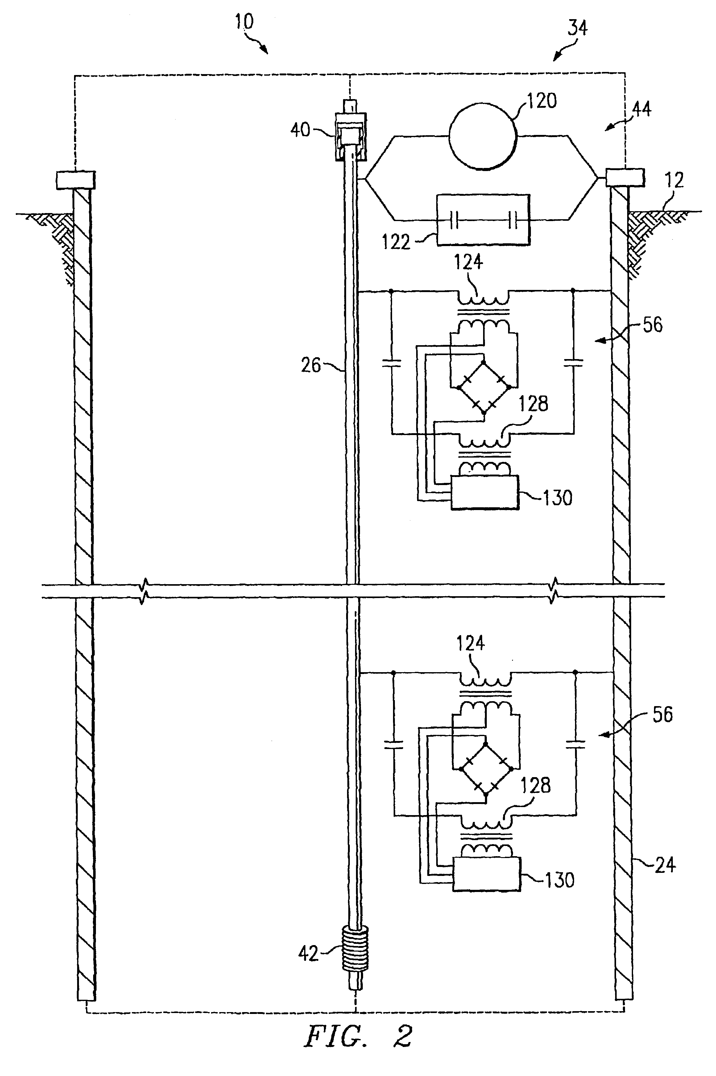
As used in the present application, a “piping structure” can be one single pipe, a tubing string, a well casing, a pumping rod, a series of interconnected pipes, rods, rails, trusses, lattices, supports, a branch or lateral extension of a well, a network of interconnected pipes, or other structures known to one of ordinary skill in the art. The preferred embodiment makes use of the invention in the context of an oil well where the piping structure comprises tubular, metallic, electrically-conductive pipe or tubing strings, but the invention is not so limited. For the present invention, at least a portion of the piping structure needs to be electrically conductive, such electrically conductive portion may be the entire piping structure (e.g., steel pipes, copper pipes) or a longitudinal extending electrically conductive portion combined with a longitudinally extending non-conductive portion. In other words, an electrically conductive piping structure is one that provides an electrica...


PUM


Abstract

A method for optimizing the production of a petroleum well is provided. The petroleum well includes a borehole, a piping structure positioned within the borehole, and a tubing string positioned within the borehole for conveying a production fluid. Production of the well is optimized by determining a flow rate of the production fluid within the tubing string and determining a lift-gas injection rate for the gas being injected into the tubing string. The flow rate and injection rate data is communicated along the piping structure of the well to a selected location, where the data is collected and analyzed. After analysis of the data, an optimum operating point for the well can be determined.

Description

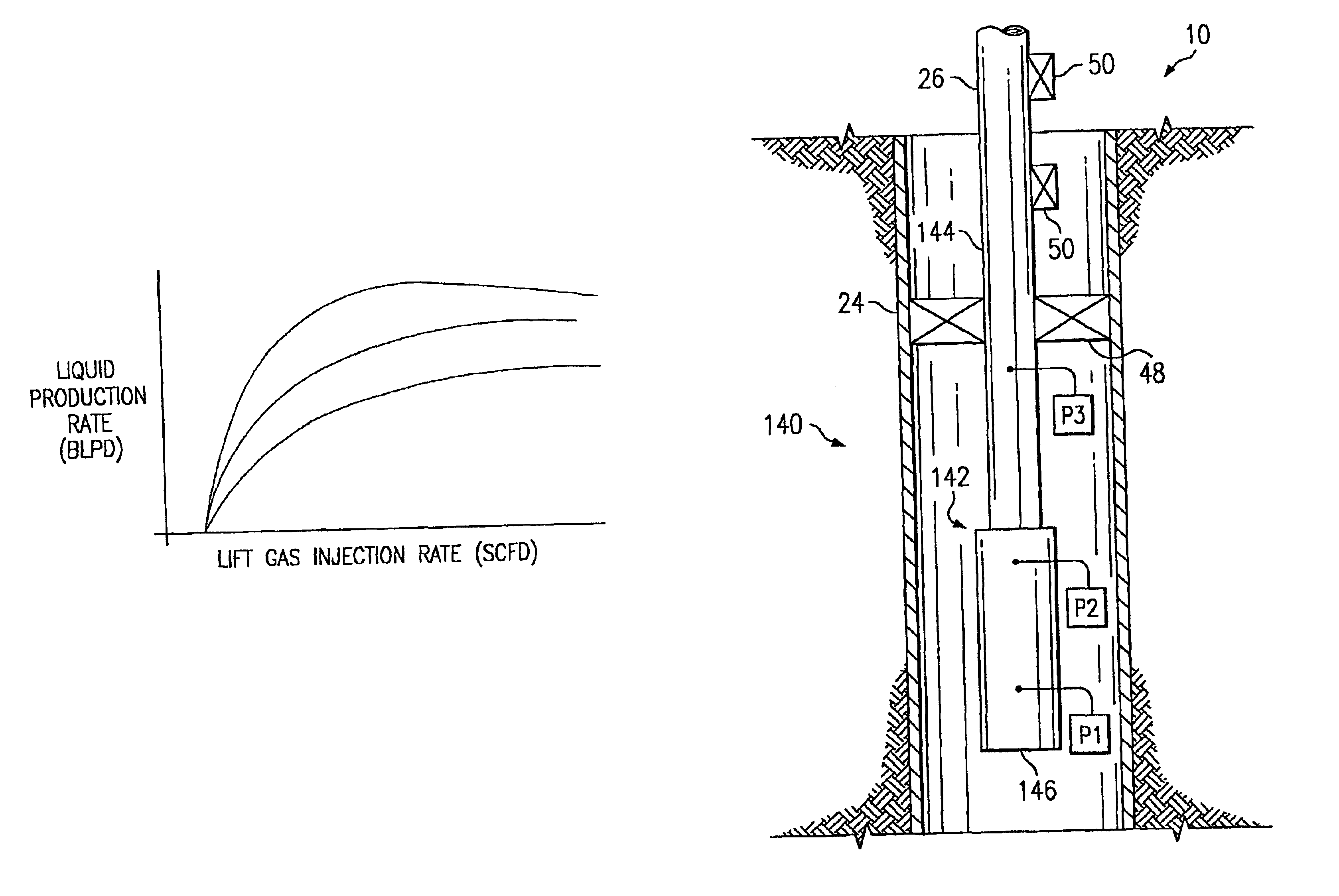
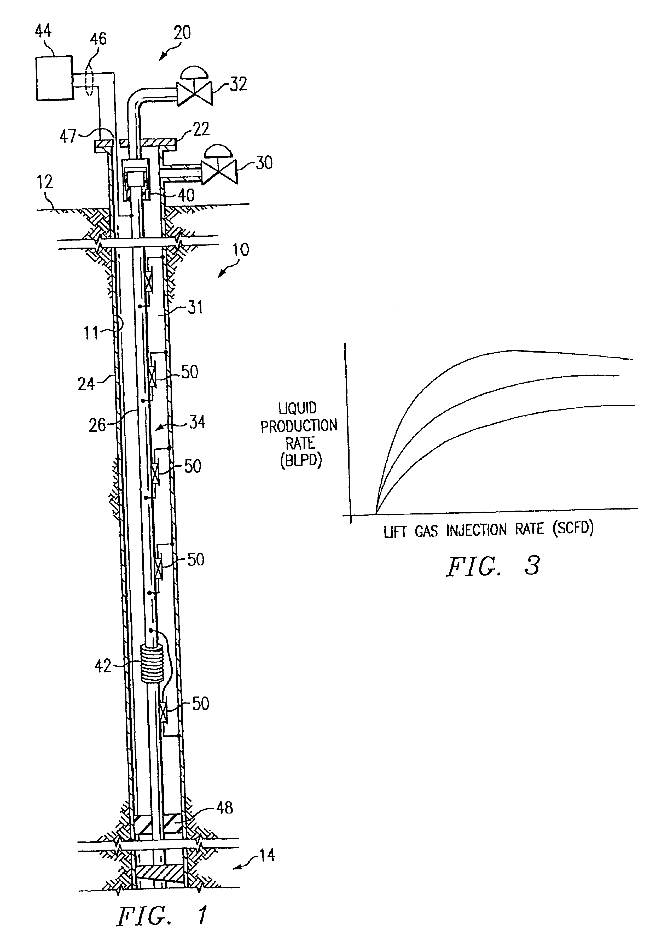
BACKGROUND OF THE INVENTION1. Field of the InventionThe present invention relates generally to a petroleum well, and in particular to a petroleum well having a downhole measurement and control system for optimally controlling production of the well or the field in which the well is situated.2. Description of Related ArtGas lift is widely employed to generate artificial lift in oil wells that have insufficient reservoir pressure to drive formation fluids to the surface. Gas is supplied to the well by surface compressors which connect through an injection control valve to the annular space between the production tubing and the casing. The gas flows down this annulus to a gas lift valve which connects the annulus between the tubing and the casing to the interior of the tubing. The gas lift valve is located just above the production zone, and the lift is generated by the combination of reduced density caused by gas bubbles in the fluid column filling the tubing, and by entrained flow of...

Claims


Application Information

Patent Timeline
Patent Type & Authority Patents(United States)
IPC IPC(8): E21B47/16E21B47/12E21B43/12E21B41/00E21B17/00E21B34/06E21B34/08E21B34/16E21B43/14E21B47/06E21B47/10H04B5/00
CPCE21B17/003E21B34/066E21B34/08E21B34/16E21B43/122E21B43/123E21B47/16E21B47/06E21B47/10E21B47/1005E21B47/101E21B47/122E21B43/14E21B47/103E21B47/107E21B47/13E21B43/1235
Inventor HIRSCH, JOHN MICHELESTEGEMEIER, GEORGE LEOHALL, JAMES WILLIAMBURNETT, ROBERT REXSAVAGE, WILLIAM MOUNTJOYCARL, JR., FREDERICK GORDON
Owner SHELL OIL CO
Why Eureka
Try Eureka