It is becoming increasingly difficult, both in terms of cost and availability, to construct conventional open reservoirs for the storage of water.
Such reservoirs typically require the construction of a dam across a river, thereby flooding vast expanses of land upstream of the dam while severely curtailing the flow of water downstream from the dam.
In light of the increasing value of water and the complexities of the various water laws across different jurisdictions, it is becoming prohibitively difficult to form an open reservoir in this manner.
However, due to the current high demand for
water storage, such opportunities are extremely rare.
While it is possible to excavate a large pit for the specific purpose of forming an
open water reservoir, such a technique requires a great expense of time and money to purchase the land, form the pit and dispose of the excavated material and soil, assuming that the excavated materials have no intrinsic economic value.
One major
disadvantage to open reservoirs is that they preempt any current or future use of the land other than to store water.
That is, as additional land surface is devoted to the storage of water in open reservoirs that same land surface is unavailable for alternative uses such as farming or open space.
A further
disadvantage of storing water in open reservoirs is the high degree of evaporative losses experienced by such reservoirs due to relatively large air / water interface.
Specifically, in
arid climates (such as those found in the Western United States), open reservoirs are subject to extremely large evaporative losses.
While previous concerns have been limited to accidental chemical spills,
petroleum leaks, polluted surface-water runoff, and the like, a more immediate
threat is that of intentional
contamination as part of a terrorist act.
Most municipal water reservoirs comprise unfenced bodies of waters in remote areas and are extremely difficult if not impossible to guard.
Furthermore, the construction of fences around existing reservoirs would be expensive and
time consuming, and even then the open reservoirs would be susceptible to
contamination from the air.
Initially, the
grout wall construction technique described by Willis (i.e., pressure-grouting clay or other “flexibilized” materials and allowing the
grout to “jel” into place) does not typically form uniform subsurface columns.
The uneven nature of the grouting process tends to form vertical sand seams between the grouted columns at the outer boundary of the
pressure injection.
These sand “lenses” or areas of high permeability formed between adjacent
grout “columns” result in grout walls that do not form substantially impermeable water barriers and that are susceptible to relatively high levels of
water leakage or seepage.
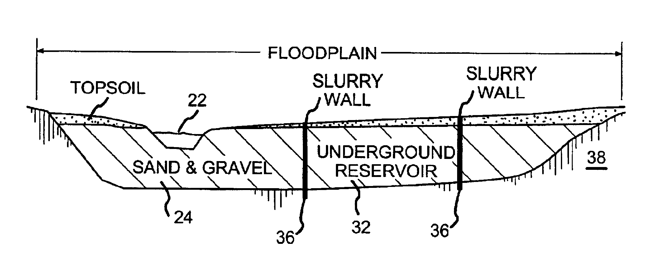
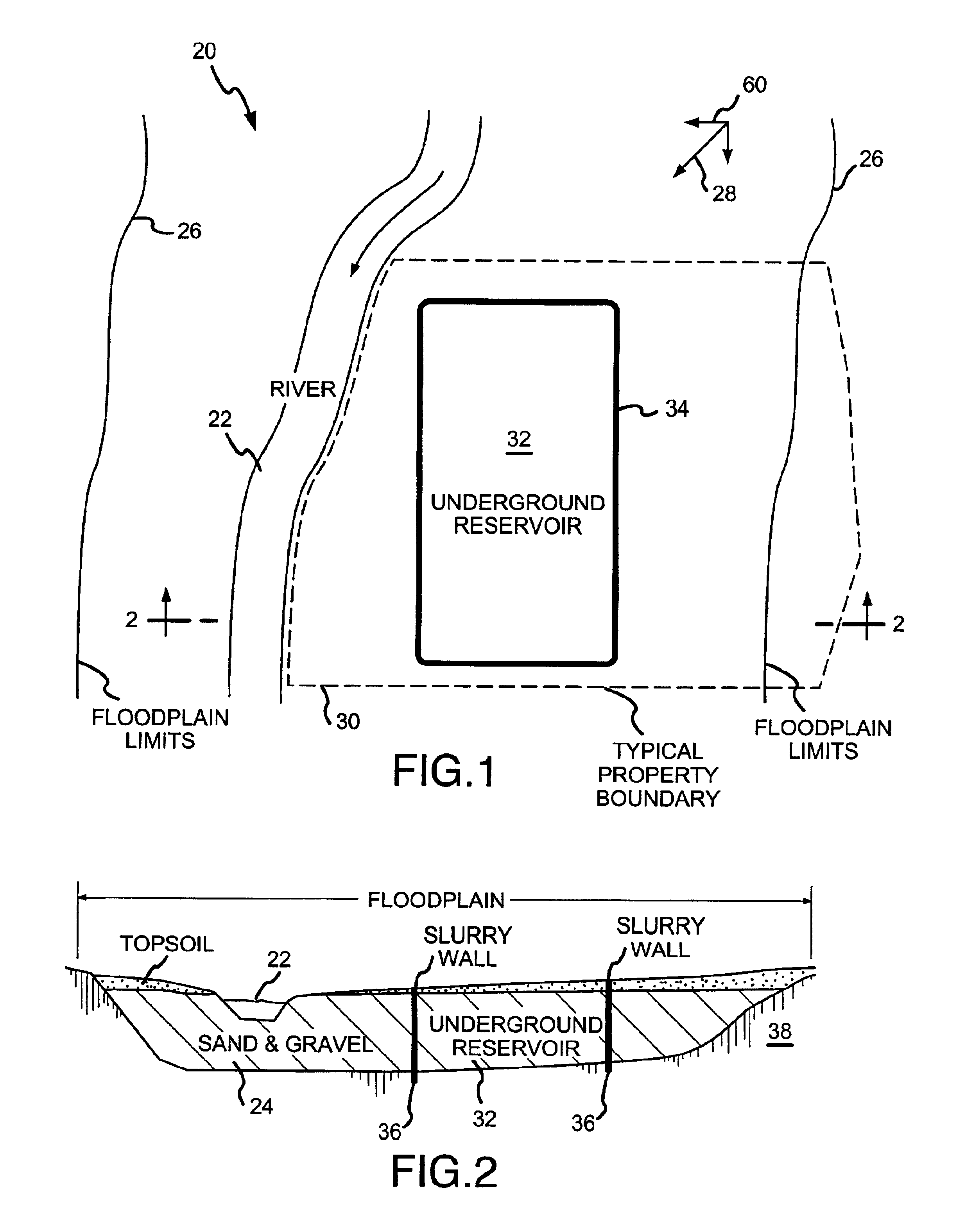
Additionally, it is not possible to key the grouted in-situ “columns” into the
bedrock or other impermeable
basement rock that defines a bottom surface of the underground reservoir.
Indeed, between the inability to form a
solid impermeable wall using the grout technique, and the inability to firmly tie the grout columns to the
bedrock defining the lower surface of the reservoir, the
water leakage rates of a reservoir built according to the technique of the Willis patent would be prohibitively high.
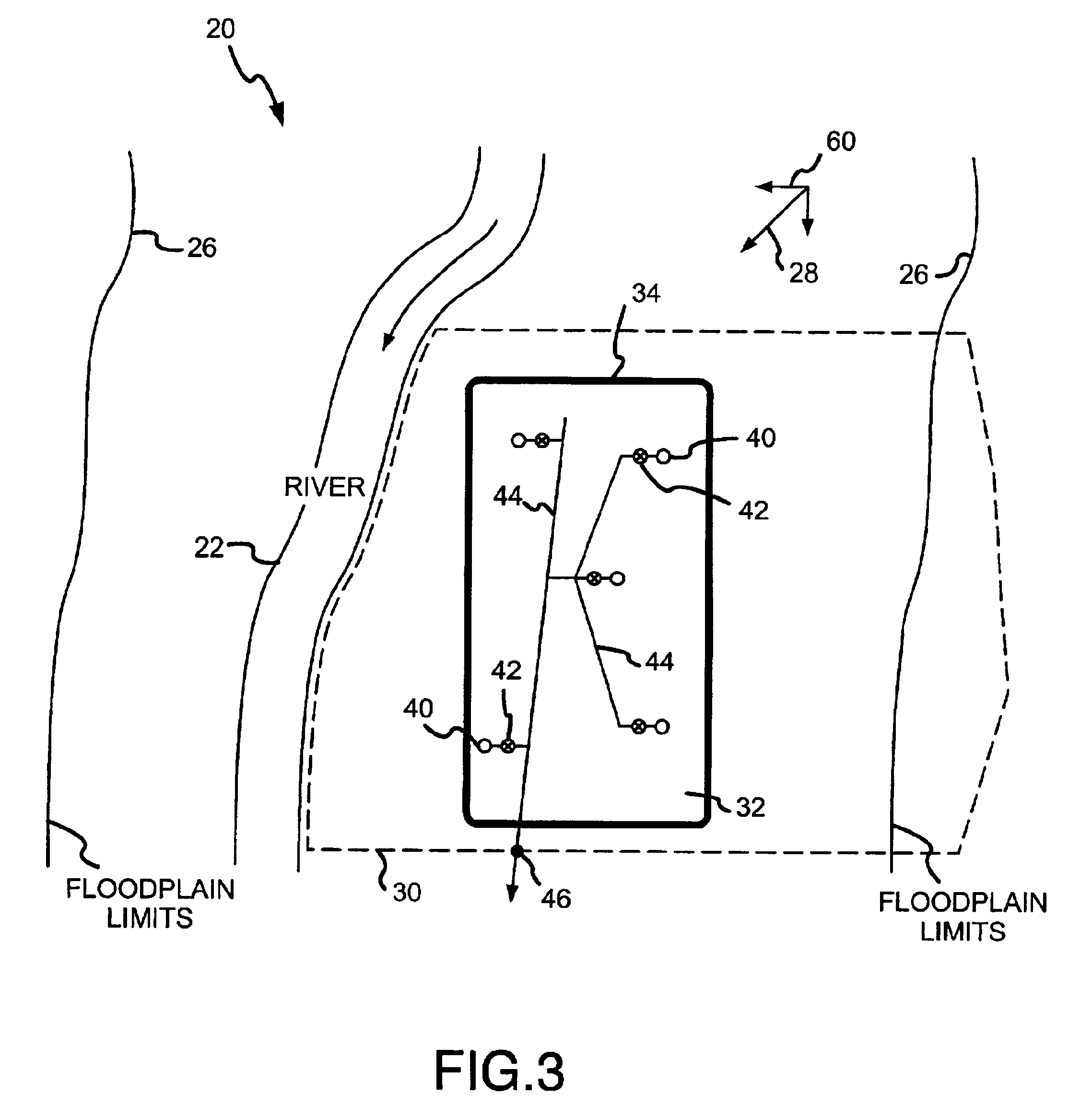
A second drawback to the technique of the Willis patent is the use of conventional wells for charging and extracting water from the underground reservoir.
Specifically, such wells are relatively inefficient when it comes to rapidly charging the reservoir with water during periods of surplus water, such as during a Spring runoff.
The same wells are similarly inefficient with respect to withdrawing water at a desired
high rate during periods when the
water level within the reservoir is low.
That is, because the typical
groundwater flow past the well is prevented within the confines of the subsurface reservoir (and thus the water within the reservoir is not pressurized to the same degree as would be found in a natural
aquifer), conventional vertical wells are unsatisfactory when it comes to extracting water at a desired rate from the underground reservoir.
A further problem associated with the underground reservoir described in the Willis patent is that there is no recognition of the problems associated with the construction of the massive subsurface walls.
Such artificial changes to the historic
water table can have severe adverse impacts on neighbors in the region.
For example, neighbors on the high side of a subsurface reservoir may experience flooded basements, while neighbors on the low side will experience a dearth of water such that alluvial wells may run dry.
Thus, while the Willis patent describes one theoretical design for a subsurface reservoir, the specifics of the Willis reservoir are not feasible due both to the inability to form a water-tight reservoir and the further inability to efficiently recharge and extract water from the reservoir.
Additionally, the grout wall construction techniques described in the Willis patent are prohibitively expensive (costing $40-$200 per
square foot of barrier), particularly when used on the scale required for an underground reservoir.
Furthermore, the Willis patent does not account for the environmental
impact that will be caused by the construction of the potentially massive subsurface walls.

