

Fuel cell power plant
- Summary
- Abstract
- Description
- Claims
- Application Information
AI Technical Summary
Benefits of technology
Problems solved by technology
Method used
Image

Examples
second embodiment
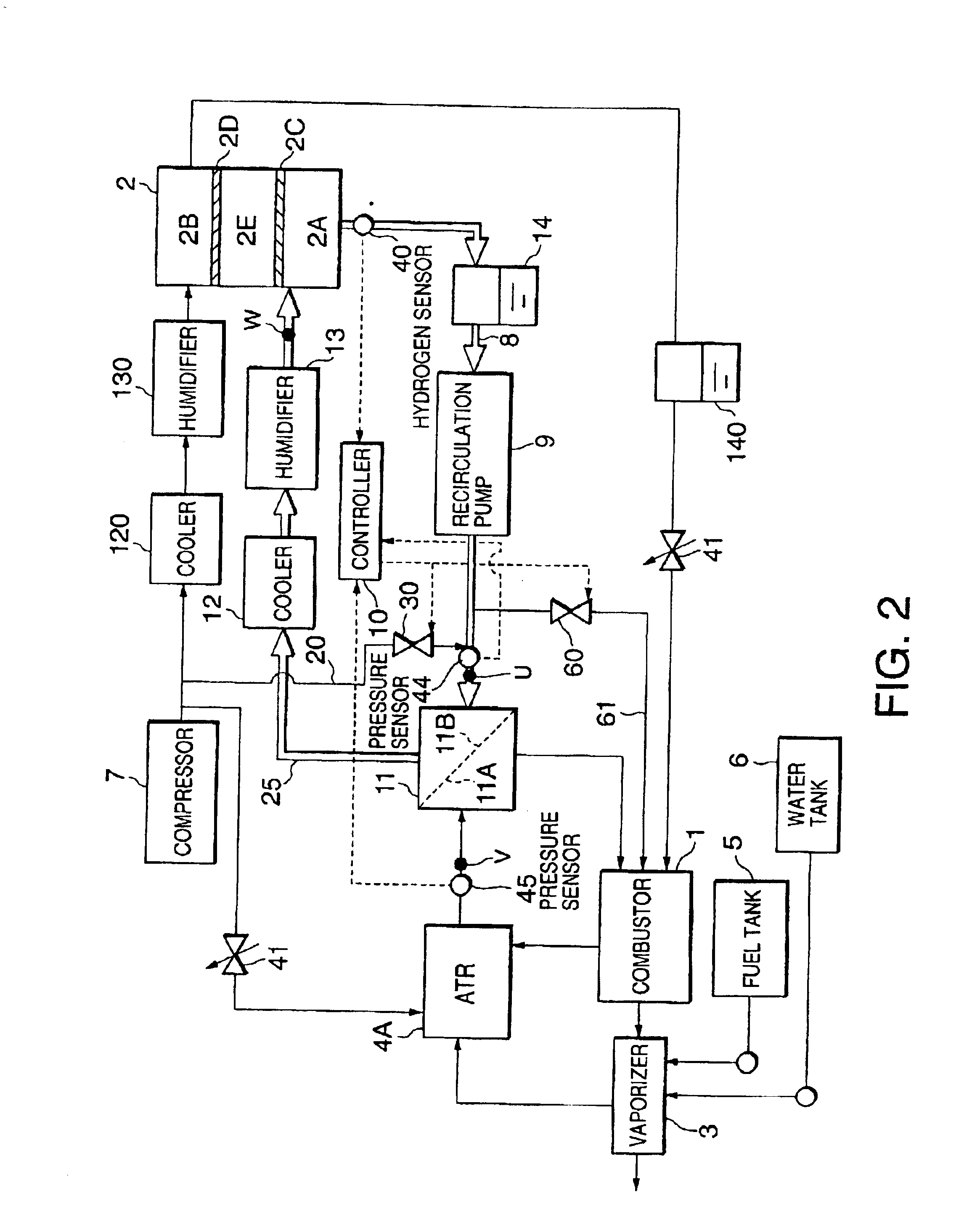
this invention will be described below with reference to FIG. 2.
In this embodiment, the reformate gas is produced using an autothermal reactor (ATR) 4A instead of the steam reformer 4.
The ATR 4A reforms the fuel by partial oxidation with a catalyst. For this purpose, air is supplied through a valve 141 from the compressor 7 to the ATR 4A. Other structure is the same as that described with respect to the first embodiment.
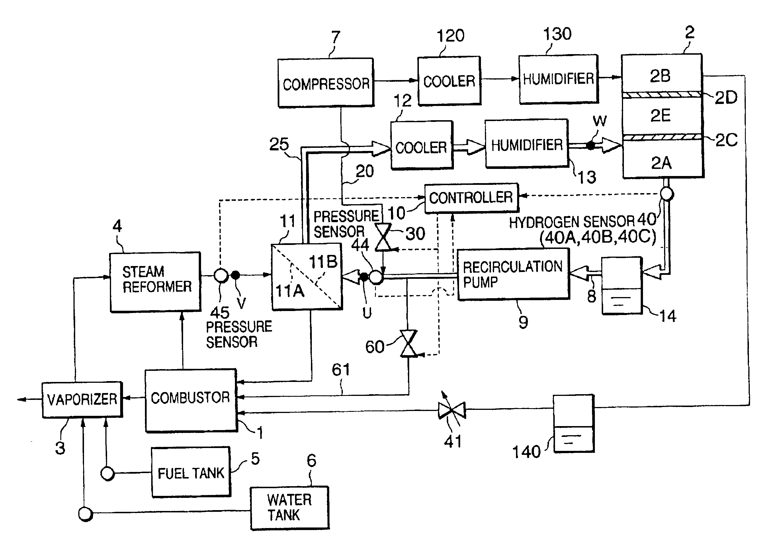
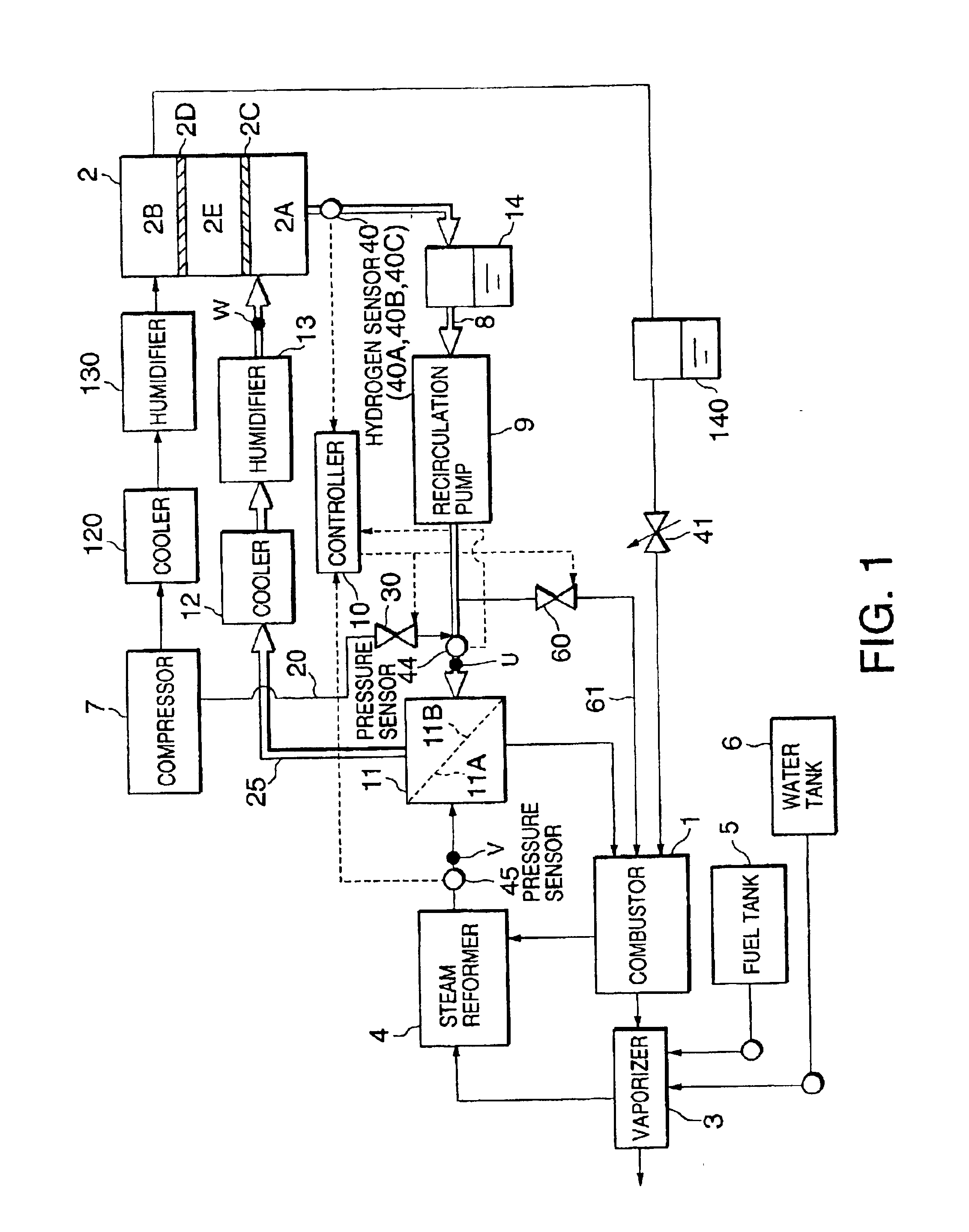
The hydrogen partial pressure and the steam pressure at the point U, the point V and the point W in FIG. 1 in the first embodiment are shown in Table 1. The hydrogen partial pressure and the steam partial pressure at the point U, the point V and the point W in FIG. 2 in the second embodiment are shown in Table 2.
TABLE 1(unit: atm)POINT UPOINT VPOINT WH20.646.321.52H2O0.571.390.47Others1.292.290.51
TABLE 2(unit: atm)POINT UPOINT VPOINT WH20.641.981.52H2O0.570.270.47Others1.290.250.51
The conditions for calculation of the hydrogen partial pressure are the same as calcula...
third embodiment
Next, this invention will be described with reference to FIG. 3.
In this embodiment, a combusted gas supply passage 21 and valves 31 and 42 are provided in order to supply combusted gas from the combustor 1 introduced into the vaporizer 3 to the hydrogen supply passage 25 instead of the intake valve 30 in the first embodiment. The valve 31 is provided in the combusted gas supply passage 21 and the valve 42 is provided in a discharge passage 43 which discharges combusted gas from the vaporizer 3 into the atmosphere. The valves 31 and 42 are operated by the controller 10.
When the hydrogen concentration in the anode effluent recirculation passage 8 rises, the controller 10 closes the valve 42, opens the valve 31 and supplies combusted gas from the combustor 1 to the hydrogen supply passage 25. The combusted gas is recirculated to the hydrogen supply passage 25 and the anode effluent recirculation passage 8 with the result that the hydrogen partial pressure on the post-separation side 11...
fourth embodiment
Next, this invention will be described with reference to FIG. 4.
According to this embodiment, instead of the intake valve 30 of the first embodiment, a valve 32 is provided which supplies a part of the cathode effluent discharged from the cathode chamber 2A of the fuel cell stack 2 to the anode effluent recirculation passage 8 through the passage 22. The valve 32 is operated by the controller 10.
When the hydrogen concentration in the anode effluent recirculation passage 8 rises, the controller 10 opens the valve 32 and supplies a part of the cathode effluent to the anode effluent recirculation passage 8. As a result, the hydrogen partial pressure on the post-separation side 11B of the membrane hydrogen separator 11 is reduced.
In the first embodiment, when the intake valve 30 is opened and air is introduced into the anode effluent recirculation passage 8 from the compressor 7, there is the possibility that the air amount supplied to the cathode chamber 2B of the fuel cell stack 2 wil...
PUM
 Abstract
Description
Claims
Application Information