Encapsulation for particle entrapment

Inactive Publication Date: 2005-01-11
TEXAS INSTR INC
View PDF8 Cites 24 Cited by
  • Summary
  • Abstract
  • Description
  • Claims
  • Application Information

AI Technical Summary

Benefits of technology

Advantages of the claimed method and system include the permanent blocking of debris generated by the debris-generating portions of the device. The debris-generating portions of the device include debris-creating regions such as the device sidewalls, and debris-harboring regions such as cavities under the device and other portions of the device, including the sidewall, that can trap debris and later release it. The blocking material not only provides permanent entrapment of debris, but entrapment of the debris is often cheaper than meth

Problems solved by technology

While scrubbing the device can remove loose particles that have not yet broken off t

Method used


Image

  • Encapsulation for particle entrapment
  • Encapsulation for particle entrapment
  • Encapsulation for particle entrapment

Examples


Example

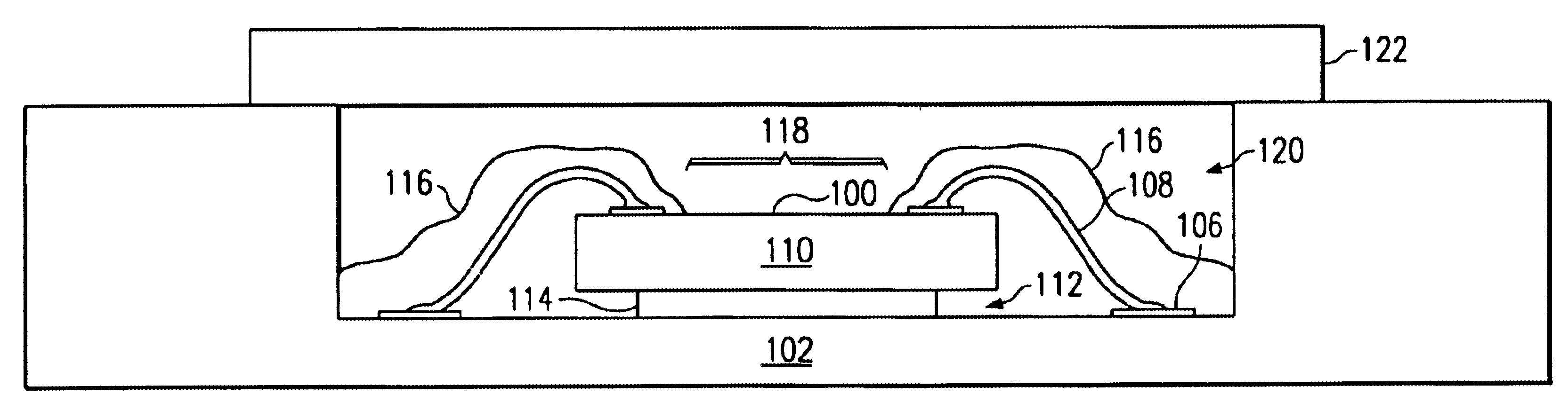
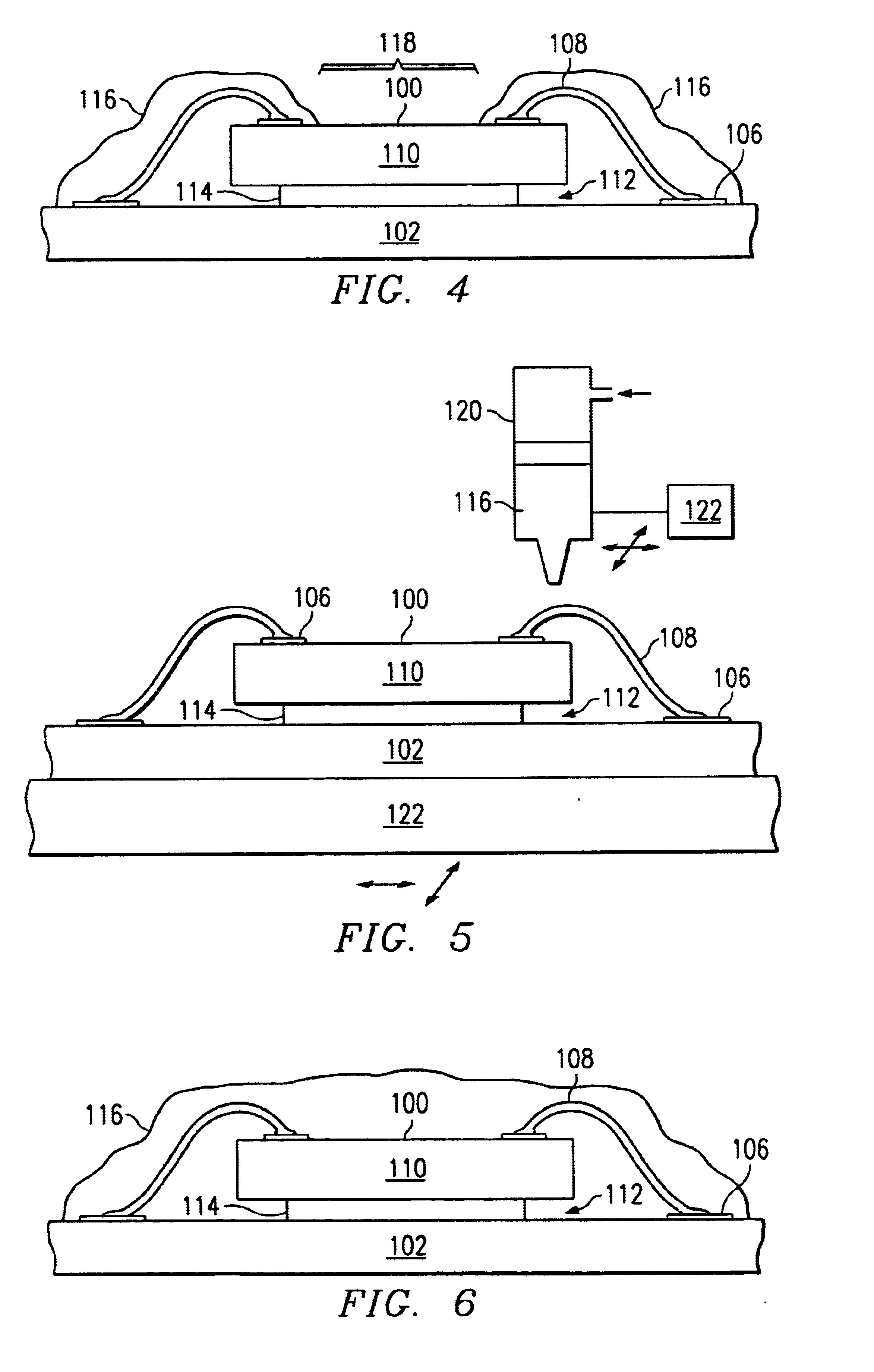
A new system and method has been developed to eliminate many of the debris-caused failures of micromechanical devices. These failures are eliminated by encapsulating the debris such that it cannot migrate to debris sensitive portions of the micromechanical device. The debris is encapsulated in place over portions of the device that are tolerant of the encapsulating material. The encapsulating material avoids regions of the micromechanical device, such as exposed moving components, that would be harmed by contact with the encapsulating material. In addition to encapsulating existing debris, the encapsulating material is also deposited over regions of the device that have been determined to generate significant quantities of debris. These regions typically include the sidewalls of the silicon substrates on which many micromechanical devices are formed.

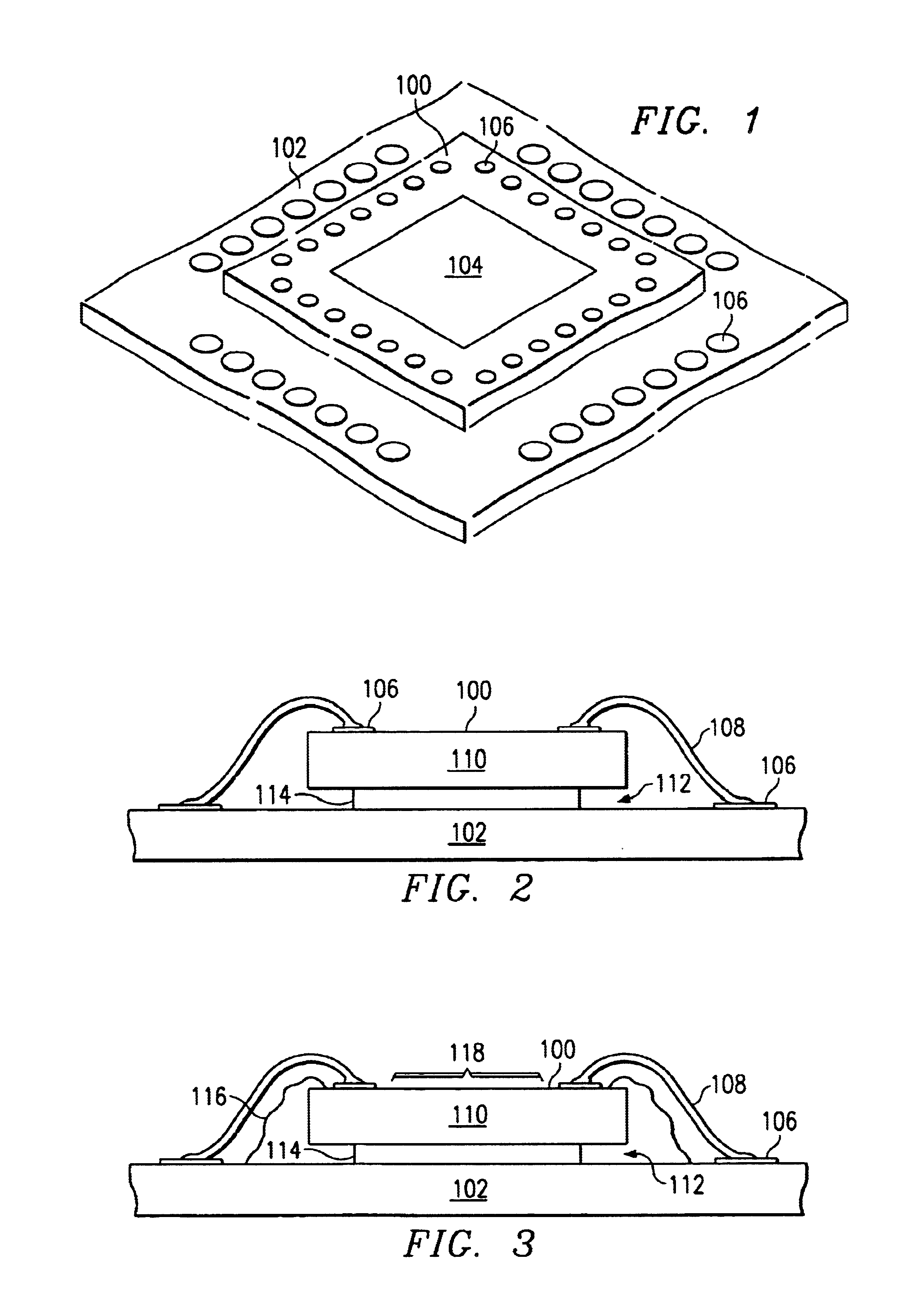
FIG. 1 is a perspective view of a micromechanical device 100 such as a digital micromirror device (DMD™) mounted to a package substrate...


PUM


Abstract

A packaged micromechanical device (100) having a blocking material (116) encapsulating debris-generating regions thereof. The blocking material (116) prevents the generation of debris that could interfere with the operation of the micromechanical device (100). Debris-generating regions of the device (100), including debris-creating sidewalls and any debris-harboring cavities, as well as electrical connections (108) linking the device (100) to the package substrate (102) are encapsulated by the blocking material (116). The blocking material (116) avoids contact with any debris-intolerant regions (118) of the device (100). A package lid (122), which is glass in the case of many DMD packages, seals the device (100) in a package cavity (120).

Description

FIELD OF THE INVENTIONThis invention relates to the manufacture of micromechanical devices, more particularly to packaging of micromechanical devices such as micromirror devices.BACKGROUND OF THE INVENTIONMicromechanical devices are small structures typically fabricated on a semiconductor wafer using techniques such as optical lithography, doping, metal sputtering, oxide deposition, and plasma etching similar to those developed for the fabrication of integrated circuits.Digital micromirror devices (DMDs), sometimes referred to as deformable micromirror devices, are a type of micromechanical device. Other types of micromechanical devices include accelerometers, pressure and flow sensors, gears and motors. While some micromechanical devices, such as pressure sensors, flow sensors, and DMDs have found commercial success, other types have not yet become commercially viable.One problem common to most micromechanical devices is the problem of particulate contamination. While some micromec...

Claims


Application Information

Patent Timeline
IPC IPC(8): H01L21/02H01L21/44G02B26/08H01L21/00H01L23/26H01L23/31
CPCB81B7/0038B81C1/00333G02B26/0833H01L21/56H01L23/31H01L23/26H01L24/48H01L2224/32014H01L2224/48091H01L2224/48227H01L2224/48465H01L2224/8592H01L2924/10253H01L23/3185H01L2924/00014H01L2924/00H01L2924/14H01L2924/181H01L2224/73265H01L2924/00012H01L2224/45099H01L2224/45015H01L2924/207
Inventor FISHER, EDWARD C.LATHAM, LAWRENCE T.
Owner TEXAS INSTR INC
Why Eureka
Try Eureka