
Overlay control for laser peening

a laser peening and overlay control technology, applied in the field of coherent energy pulses, can solve the problems of inability to meet industrial needs, high explosive materials, and inability to use high pressure gases in extreme environments, and achieve the effect of more consistent and repeatable laser peening results

Inactive Publication Date: 2005-01-11
LSP TECH INC
View PDF4 Cites 12 Cited by
  • Summary
  • Abstract
  • Description
  • Claims
  • Application Information

AI Technical Summary

Benefits of technology

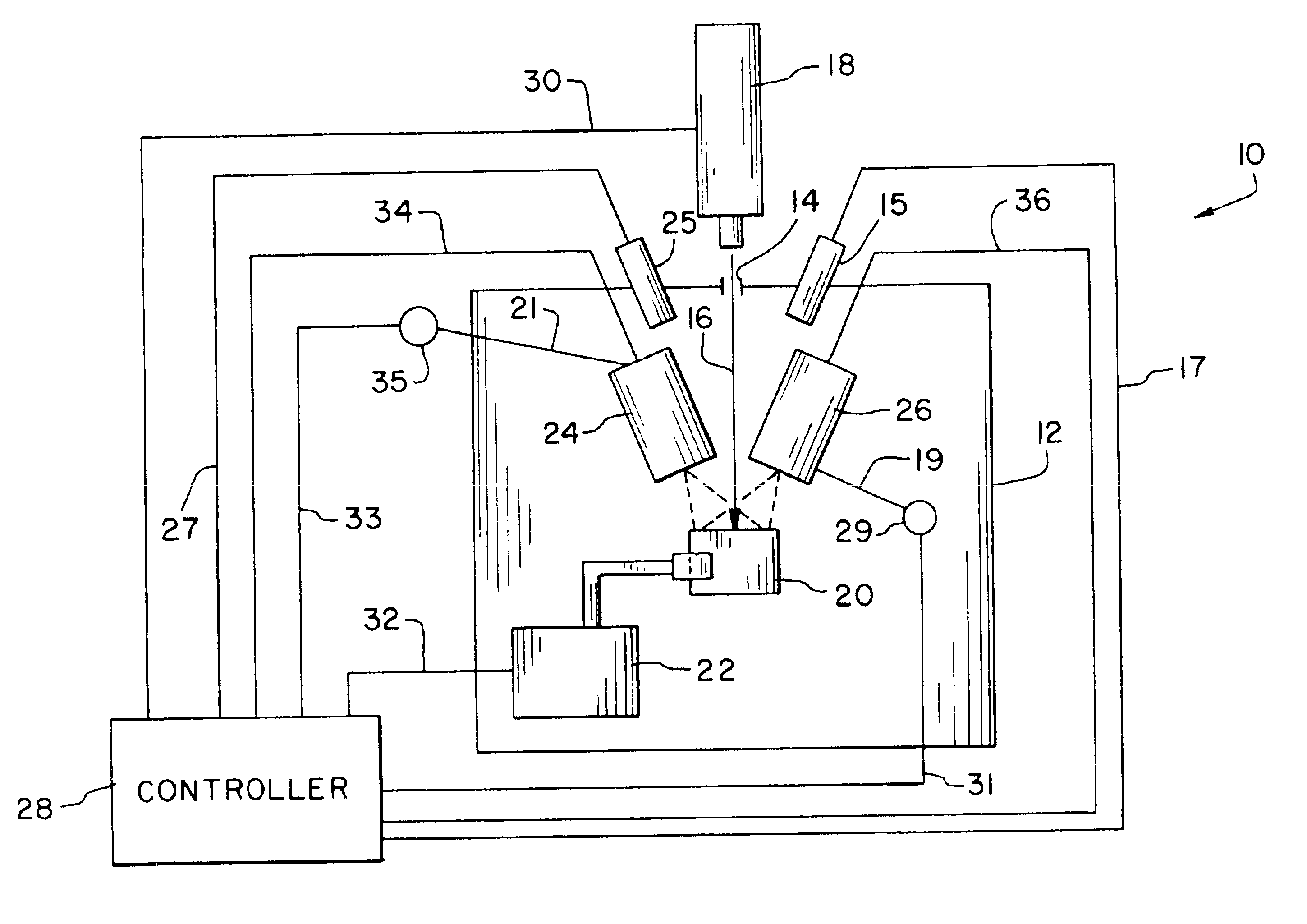
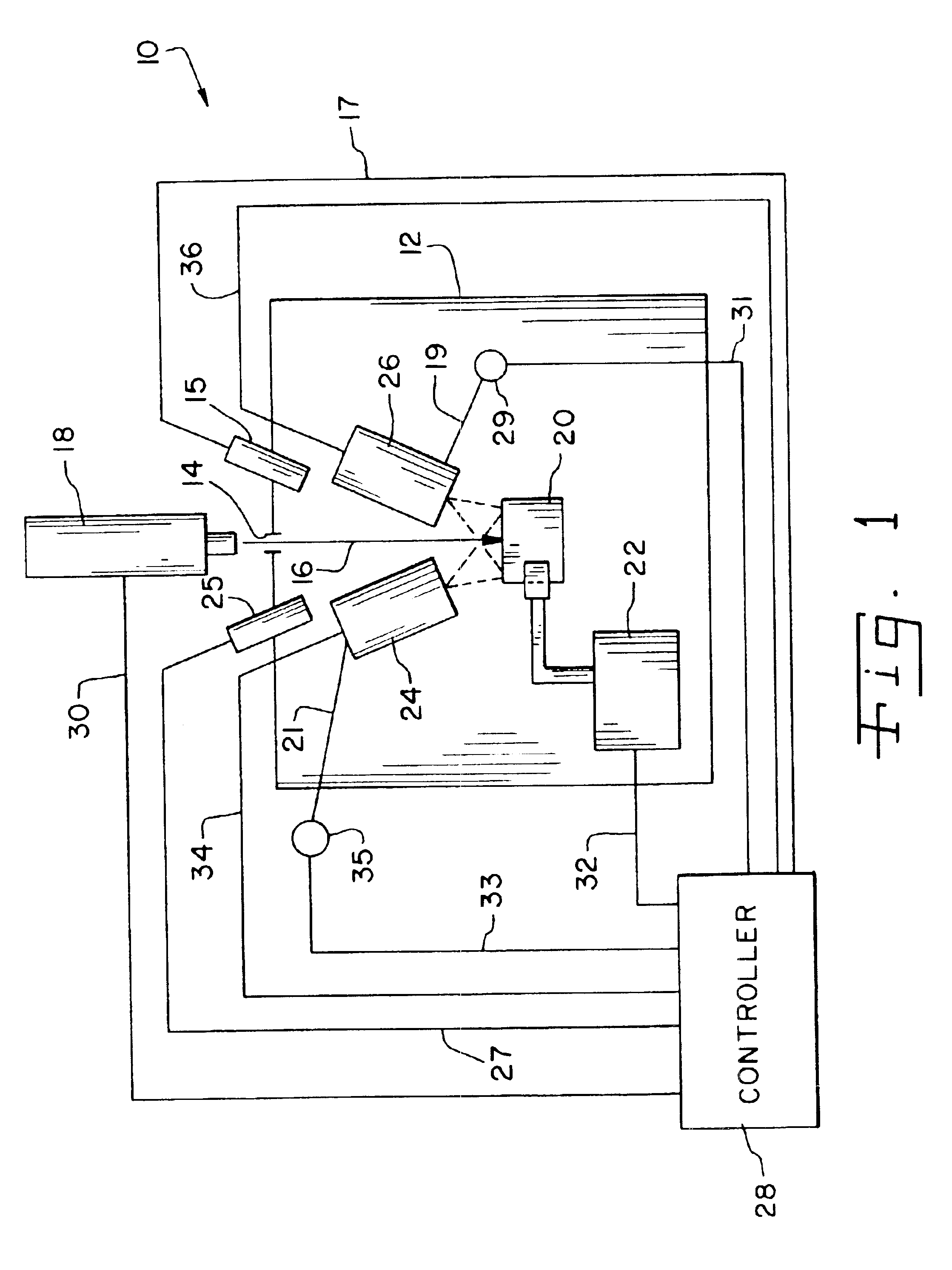
An advantage of the present invention is that it provides a method to ensure a consistent thickness of an overlay, which provides more consistent and repeatable laser peening results within the workpiece.
is that it provides a method to ensure a consistent thickness of an overlay, which provides more consistent and repeatable laser peening results within the workpiece.
Another advantage of the present invention is that the control computer can control the timing of the application of the paint and overlay water by measuring the thickness during application of these overlays.
Yet another advantage of the present invention is that the control computer can make adjustments to the control valves to modify the thickness of the paint and overlay water.
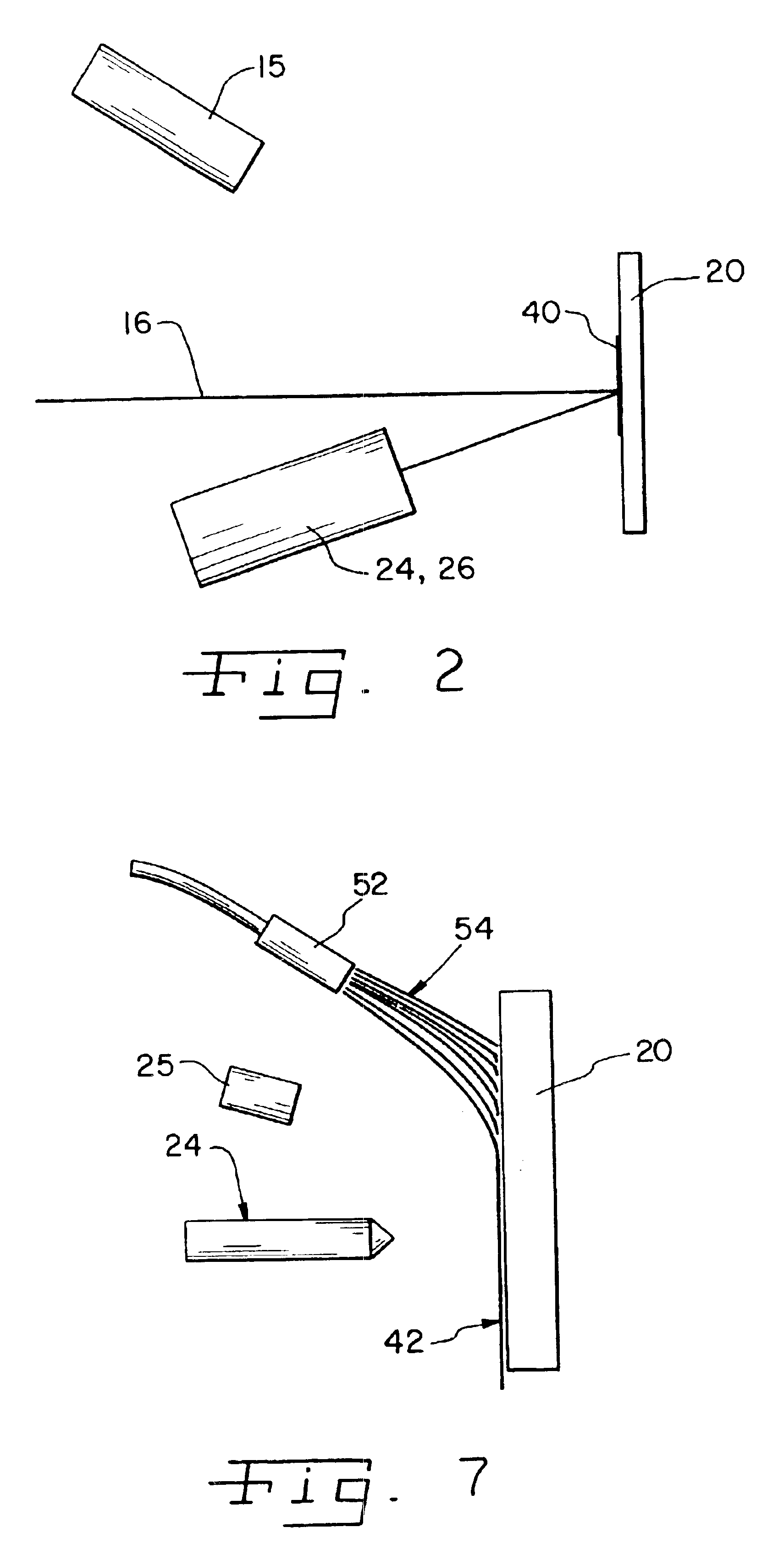
A further advantage of the present invention is that the control computer can modify the thickness of the overlays applied to the surface of the workpiece by use of an tamping device.

Problems solved by technology

For example: (a) it is difficult and costly to shock process non-planar surfaces and complicated geometries, (b) storage and handling of the high explosive materials and high pressure gases pose a hazard, (c) the processes are difficult to automate and thus fail to meet some industrial needs and (d) high explosive materials and high pressure gases cannot be used in extreme environments such as high temperatures and high vacuum.
Since the shot or beads might get into surrounding machinery and cause damage, shot peening usually cannot be used in a manufacturing line.
Ordinarily such shot peening cannot be used on machined surfaces without a high likelihood of damaging them.
In addition, shot peening has problems maintaining consistency of treatment caused by inherent wear of the shot by the shot peening equipment.
Additionally, it is easy to laser peen the workpiece repetitively.
A laser beam is directed to pass through the overlay water and is absorbed by the paint, causing a rapid vaporization of a thin layer of the paint and the generation of a high-amplitude shock wave in the workpiece.
This method has been successfully implemented into laser peening equipment and has dramatically decreased the processing time and cost; however, the variability in the thicknesses and / or uniformity of the paint or overlay water can potentially lead to differences in the resultant residual stresses in the workpiece and thus change the fatigue life capabilities of the laser-peened workpiece.

Method used


Image

  • Overlay control for laser peening
  • Overlay control for laser peening
  • Overlay control for laser peening

Examples


Embodiment Construction

The improvements in fatigue life produced by laser peening are the results of residual compressive stresses developed in the irradiated surface retarding fatigue crack initiation and / or slowing the crack propagation rate. A crack front is the leading edge of a crack as it propagates through a solid material. Changes in the shape of a crack front and slowing of the crack growth rate when the crack front encounters the laser shock zone in a laser peening condition have been shown. Laser peening is an effective method of increasing fatigue life in metals by treating fatigue critical regions. As to what effect the tensile residual stresses surrounding the laser shocked region would have on crack initiation, a previous study is described in “Shock Waves and High Strained Rate Phenomena in Metals” by A. H. Clauer, J. H. Holbrook and B. P. Fairand, ed. by M. S. Meyers and L. E. Murr, Plenum Press, New York (1981), pp. 675-702. Described in the above reference are the effects of laser peeni...


PUM

PropertyMeasurementUnit
Thicknessaaaaaaaaaa
Pressureaaaaaaaaaa
Transparencyaaaaaaaaaa

Abstract

A method of controlling the application of laser peening overlays on the surface of a workpiece to reduce the variability of shock waves generated therein, comprises applying an energy-absorbing overlay to a portion of the surface of a workpiece, measuring the thickness of the energy-absorbing overlay in at least one location on the energy-absorbing overlay, applying a transparent overlay material over the energy-absorbing overlay, measuring the thickness of the transparent overlay in at least one location on the transparent overlay, determining if the measured values for each overlay is within a specified range, and directing a pulse of coherent energy to the workpiece to create a shock wave therein when the measured values are within the specified range.

Description

BACKGROUND OF THE INVENTION1. Field of the InventionThe present invention relates to the use of coherent energy pulses, as from high-peak-power pulsed lasers used for the laser peening of solid materials and, more particularly, to methods and apparatus to control the application of the overlays applied for laser peening (also called laser shock peening, laser shock processing, and shock processing). The invention is especially useful for reducing the variability of the thickness of the overlays applied to the surface of the workpiece being laser shock peened.2. Description of the Related ArtOld methods for shock processing of solid materials typically involve the use of high explosive materials or high-pressure gases, which are used to accelerate a plate, that strikes the solid material to produce shock waves therein. Such methods have several disadvantages. For example: (a) it is difficult and costly to shock process non-planar surfaces and complicated geometries, (b) storage and h...

Claims


Application Information

Patent Timeline
IPC IPC(8): B23K26/02B23K26/03B23K26/18C21D10/00
CPCB23K26/032B23K26/18B23K26/009C21D10/005C21D2221/00
Inventor DYKES, STEVEN E.CLAUER, ALLAN H.DULANEY, JEFF L.LAHRMAN, DAVID F.O'LOUGHLIN, MARK
Owner LSP TECH INC
Learn More