Display device

a display device and display technology, applied in the field of display devices, can solve the problems of reducing contrast ratio, flat display, deteriorating image quality, etc., and achieve the effect of high contrast ratio

Inactive Publication Date: 2005-01-11
NITTO DENKO CORP
View PDF13 Cites 84 Cited by
  • Summary
  • Abstract
  • Description
  • Claims
  • Application Information

AI Technical Summary

Benefits of technology

The amount of the light going out of the display device is slight because the light passes through the color filter unit a plurality of times in such a manner that light at wavelengths in the visible region excluding the wavelength range of emitted light is absorbed whenever the light passes through the color filter unit. Hence, black display becomes darker even under a bright environment, so that a higher contrast ratio can be achieved.

Problems solved by technology

Hence, the OLED display is flat and lightweight because it is unnecessary to provide any auxiliary light source such as a backlight.
Hence, when the OLED display is used under a bright environment, there is a problem that image quality deteriorates because of reflection of a surrounding scene in the mirror, or there is a problem that the contrast ratio is lowered because of spoilage of black display by reflection of external light.
In addition, under a bright environment, the color changing mediums are excited to be brighter by external light, so that black display is spoiled.
There is however a problem that efficiency in utilization of light is lowered because light is absorbed to color filters.
Hence, reflection of external light cannot be suppressed perfectly.
In the existing organic light-emitting diodes, however, it cannot be said that color purity is sufficient because the wavelength distributions of emitted light are broad and gentle in accordance with the colors.

Method used


Image

  • Display device
  • Display device
  • Display device

Examples


embodiment 1

(Embodiment 1)

FIG. 7 is a block diagram typically showing the overall layout of a display device 1 according to this embodiment. FIG. 8 is an equivalent circuit diagram of an active matrix formed in a display portion of the display device 1.

As shown in FIG. 7, the display device 1 has a display portion 2 provided in a substantially central portion of a substrate 6. A data drive circuit 3 for supplying an image signal to each data line 7 is disposed on an upper side of the display portion 2. A scanning drive circuit 4 for supplying a scanning signal to each gate line 8 is disposed on a left side of the display portion 2. Each of these drive circuits 3 and 4 is constituted by a shift register circuit, a level shifter circuit, an analog switch circuit, etc. as represented by a complementary circuit using N-channel and P-channel TFTs (Thin Film Transistors).

Like an active matrix liquid-crystal display device, the display device 1 has a plurality of gate lines and a plurality of data lin...

embodiment 2

(Embodiment 2)

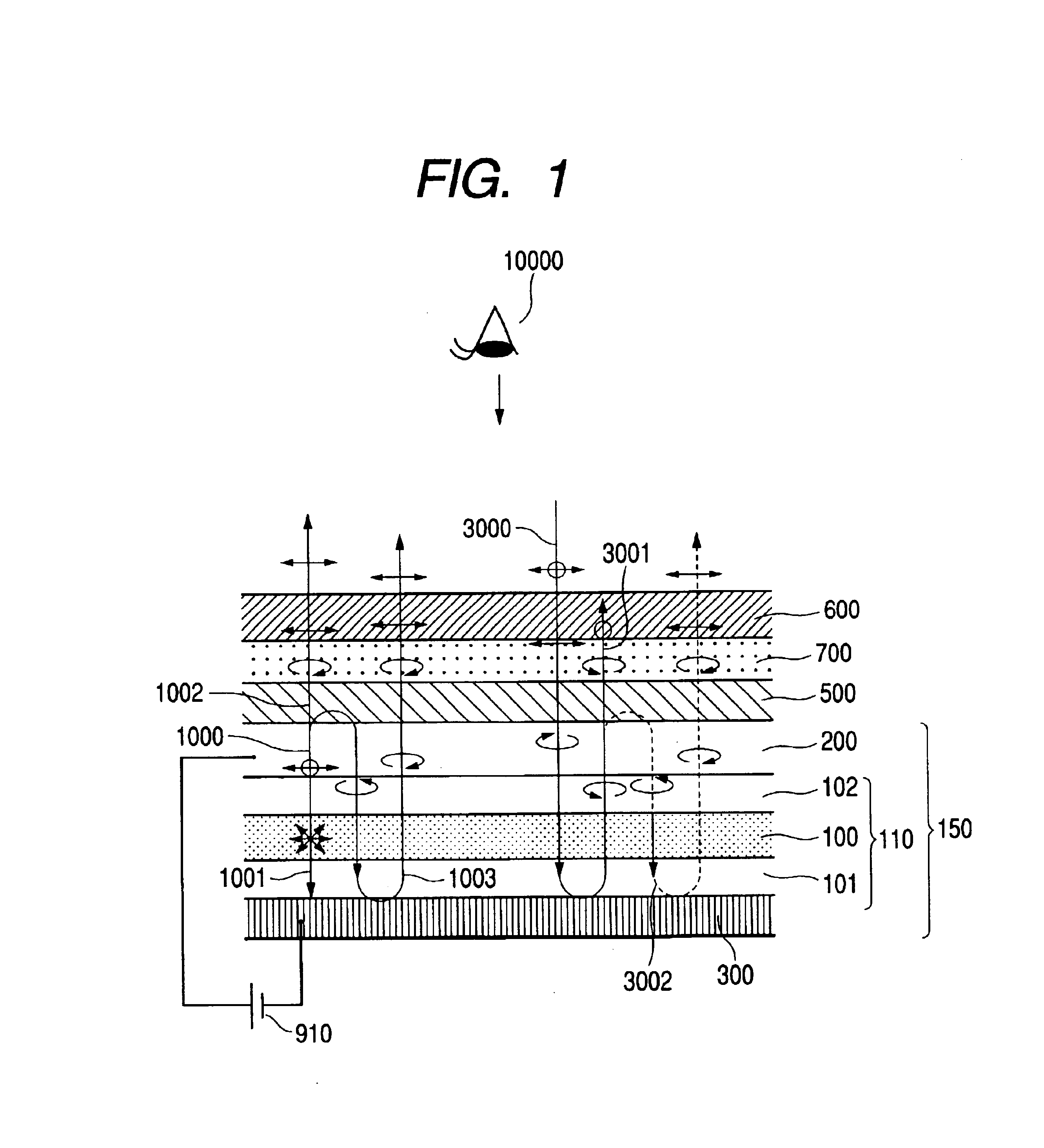
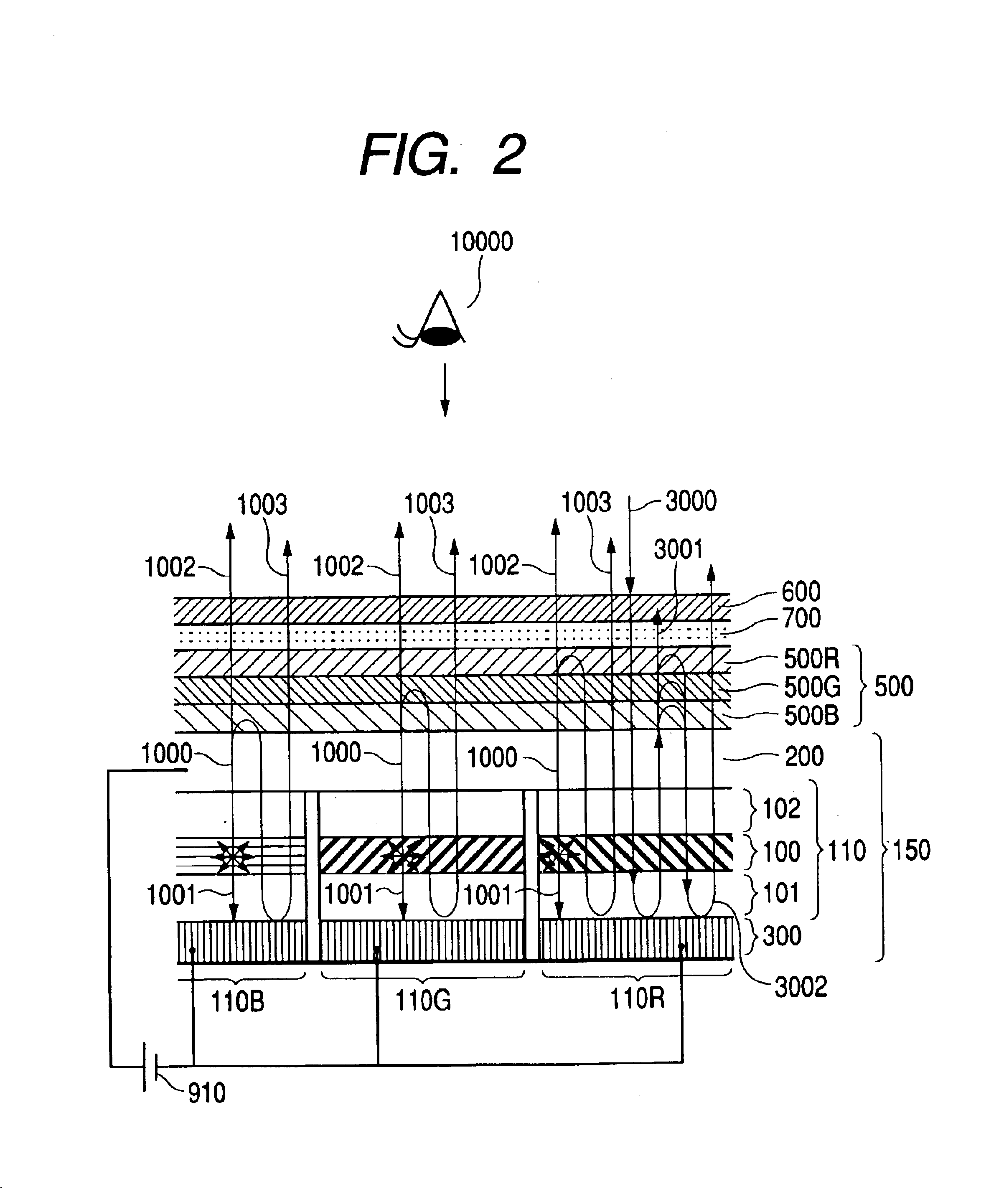
A display device according to this embodiment will be described below. FIG. 14 is a partly sectional view schematically showing the display device. The display device is basically configured in the same manner as in Embodiment 1 except that a color filter unit is provided. Hence, like numerals refer to like parts for the sake of omission of duplicated description.

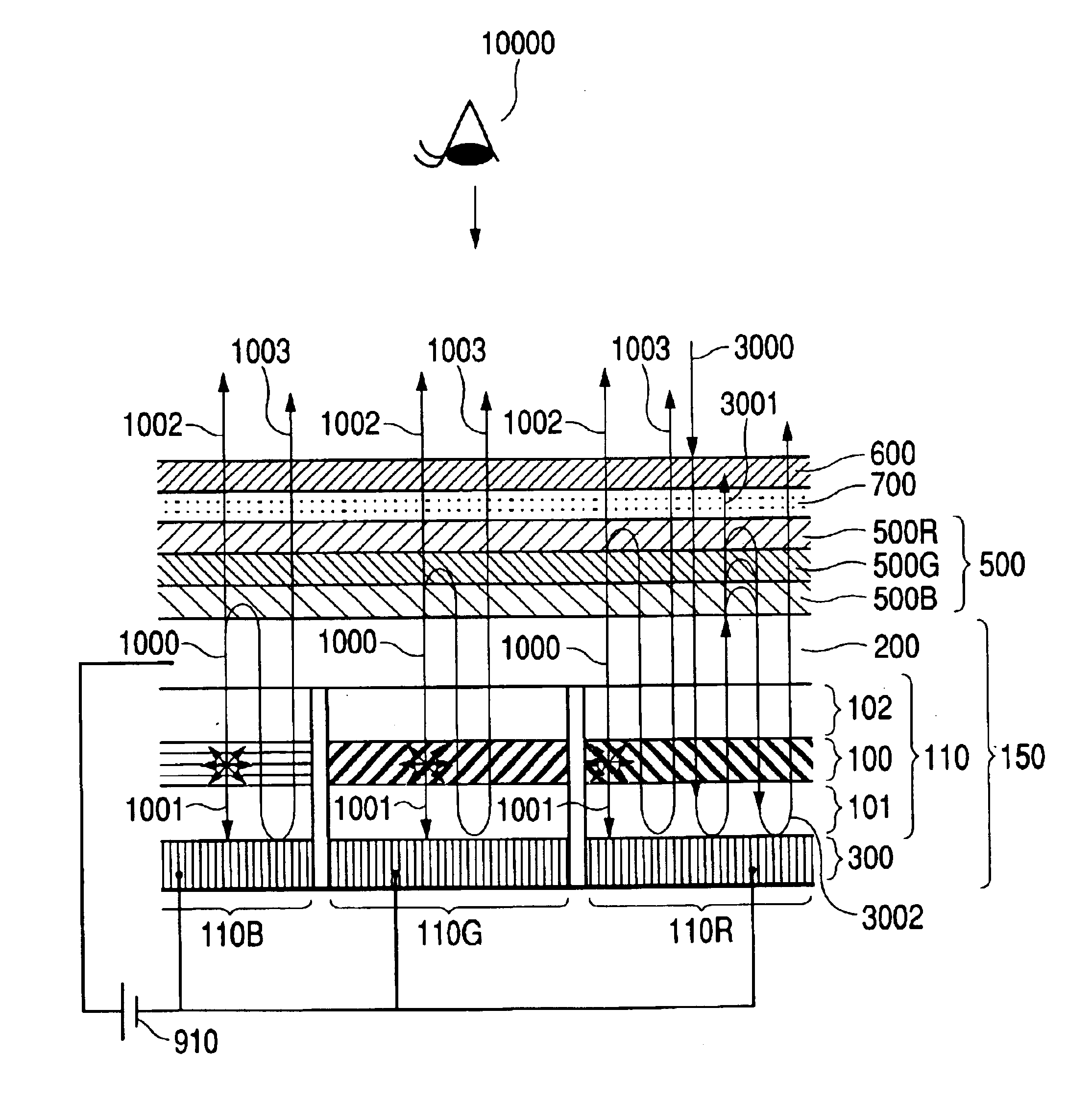
As shown in FIG. 14, the display device according to this embodiment is configured in the same manner as in Embodiment 1 described with reference in FIG. 11, except that a color filter unit 900 capable of transmitting light in a predetermined wavelength range but absorbing light at wavelengths in the visible region excluding the predetermined wavelength range is disposed between the second substrate 90 and the polarized light separating unit 500.

The construction of the color filter unit 900 may be obtained, for example, by dividing the color filter unit 900 into color filters provided on the second substrate 9...

embodiment 3

(Embodiment 3)

FIG. 16 is a partly sectional view schematically showing a display device according to this embodiment. The basic configuration of the display device is the same as that of the display device according to Embodiment 2 except that the color of light emitted from the organic layer is white. Like numerals refer to like parts for the sake of omission of duplicated description.

As shown in FIG. 16, the display device according to this embodiment is configured in the same manner as in Embodiment 2 described with reference to FIG. 14, except that all red light-emitting, green light-emitting and blue light-emitting organic layers into which the organic layer is divided are replaced by white light-emitting organic layers 110W.

The organic layer for achieving white light emission may be constituted by a laminate of a plurality of light-emitting layers different in emitted light color or may be constituted by a light-emitting layer doped with dyes different in emitted light color.

A...


PUM


Abstract

A display device having: a light-emitting layer 100; a light-reflecting member disposed on a back surface of the light-emitting layer; a polarized light separating unit 500 provided so that light in a predetermined wavelength range corresponding to light emitted from the light-emitting layer is separated into two kinds of polarized light components by reflection and transmission; a polarizer 600; and a retarder 700, the polarized light separating unit 500, the polarizer 600 and the retarder 700 being disposed on a front surface side of the light-emitting layer.

Description

The present invention is based on Japanese Patent Application No. 2001-384413, which is incorporated herein by reference.BACKGROUND OF THE INVENTION1. Field of the InventionThe present invention relates to a display device for performing display by controlling light-emitting operations of light-emitting elements, and particularly to a display device having light-emitting elements such as organic light-emitting diodes each having a light-reflecting surface on a back surface of a light-emitting layer.2. Related ArtAn organic light-emitting diode is a device for emitting light in such a manner that positive or negative electric charge is injected into a light-emitting layer of an organic thin film to thereby convert electric energy into light energy.A display device constituted by organic light-emitting diodes (hereinafter referred to as “OLED display”) is of a self-luminous type to be different from a non-luminous type display device represented by a liquid-crystal display device. Hen...

Claims


Application Information

Patent Timeline
Patent Type & Authority Patents(United States)
IPC IPC(8): H01L51/50H01L51/52H01L27/32H01L27/28G02B5/20G02B5/30G02B27/28G09F9/00G09F9/30H05B33/02
CPCH01L51/5281H01L51/5262H01L27/3211H01L27/322H01L27/3244H10K59/35H10K59/38H10K59/12H10K50/85H10K50/86
Inventor AIZAWA, KAORUADACHI, MASAYAKOMURA, SHINICHI
Owner NITTO DENKO CORP
Why Eureka
Try Eureka