Use of MWD assembly for multiple-well drilling

a technology for drilling multiple wells and assemblies, applied in the direction of instruments, borehole/well accessories, surveys, etc., can solve the problem that magnetometers cannot be used to maintain

Inactive Publication Date: 2005-01-11
BAKER HUGHES INC
View PDF25 Cites 31 Cited by
  • Summary
  • Abstract
  • Description
  • Claims
  • Application Information

AI Technical Summary

Benefits of technology

The present invention is a method of using a gyro-MWD device to control the orientation of a borehole and maintain its position in a desired relation to a preexisting borehole. Such requirements are common in an injection wellbore used in secondary recovery operations for injecting a fluid such as steam, CO2, water or a polymer in proximity to a perforated cased production wellbore. Due to the presence of casing, magnetometers cannot be used to maintain the desired relative position of the injection wellbore and the production wellbore. With the gyro-MWD device, a positional accuracy of three meters or less may be maintained while drilling the injection wellbore.

Problems solved by technology

Due to the presence of casing, magnetometers cannot be used to maintain the desired relative position of the injection wellbore and the production wellbore.

Method used


Image

  • Use of MWD assembly for multiple-well drilling
  • Use of MWD assembly for multiple-well drilling
  • Use of MWD assembly for multiple-well drilling

Examples


Embodiment Construction

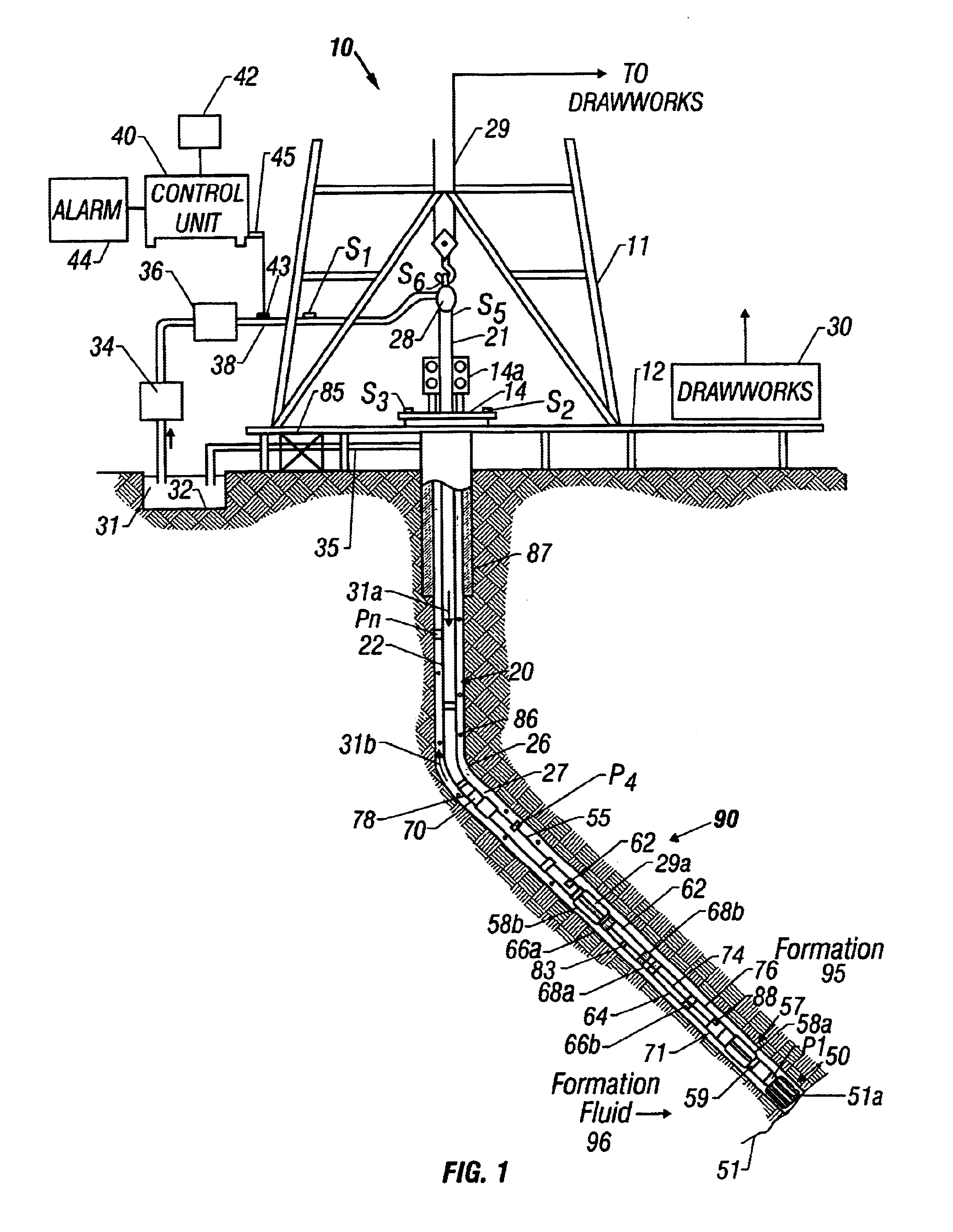
FIG. 1 shows a schematic diagram of a drilling system 10 having a bottom hole assembly (BHA) or drilling assembly 90 that includes gyroscope(s) according to the present invention. The BHA 90 is conveyed in a borehole 26. The drilling system 10 includes a conventional derrick 11 erected on a floor 12 which supports a rotary table 14 that is rotated by a prime mover such as an electric motor (not shown) at a desired rotational speed. The drill string 20 includes a tubing (drill pipe or coiled-tubing) 22 extending downward from the surface into the borehole 26. A drill bit 50, attached to the drill string 20 end, disintegrates the geological formations when it is rotated to drill the borehole 26. The drill string 20 is coupled to a drawworks 30 via a kelly joint 21, swivel 28 and line 29 through a pulley (not shown). Drawworks 30 is operated to control the weight on bit (“WOB”), which is an important parameter that affects the rate of penetration (“ROP”). A tubing injector 14a and a re...


PUM


Abstract

This invention provides a measurement-while-drilling (MWD) downhole assembly for use in drilling boreholes which utilizes gyroscopes, magnetometers and accelerometers for determining the borehole inclination and azimuth during the drilling of the borehole. With the present invention, a secondary borehole for secondary recovery operations may be drilled with accuracy in proximity to a cased producing borehole.

Description

FIELD OF THE INVENTIONThis invention relates generally to bottom hole assemblies for drilling oilfield wellbores and more particularly to the use of gyroscopic and other sensors to determine wellbore direction during the drilling of the wellbores and to the correction of data from such sensors.BACKGROUND OF THE INVENTIONTo obtain hydrocarbons such as oil and gas, wellbores (also referred to as the boreholes) are drilled by rotating a drill bit attached at the end of a drilling assembly generally referred to as the “bottom hole assembly” or the “drilling assembly.” A large portion of the current drilling activity involves drilling highly deviated and substantially horizontal wellbores to increase the hydrocarbon production and / or to withdraw additional hydrocarbons from the earth's formations. The wellbore path of such wells is carefully planned prior to drilling such wellbores utilizing seismic maps of the earth's subsurface and well data from previously drilled wellbores in the ass...

Claims


Application Information

Patent Timeline
Patent Type & Authority Patents(United States)
IPC IPC(8): E21B47/022E21B47/02G01C19/00G01C19/38
CPCG01C19/38E21B47/022
Inventor ESTES, ROBERT A.
Owner BAKER HUGHES INC
Why Eureka
Try Eureka