Very low temperature refrigeration system with controlled cool down and warm up rates and long term heating capabilities

a refrigeration system and very low temperature technology, applied in the direction of defrosting, defrosting apparatus, instruments, etc., can solve the problem of never allowing defrost return bypass, and achieve the effect of increasing the throughput of a vacuum system, increasing the defrost operating time, and small temperature rang

Inactive Publication Date: 2005-01-18
EDWARDS VACUUM LLC
View PDF4 Cites 44 Cited by
  • Summary
  • Abstract
  • Description
  • Claims
  • Application Information

AI Technical Summary

Benefits of technology

An advantage of the present invention is that it heats the coils of the refrigeration system internally. Conventional systems use an exterior heat source to heat the coils of the refrigeration system.
is that it heats the coils of the refrigeration system internally. Conventional systems use an exterior heat source to heat the coils of the refrigeration system.
Another advantage is that the present invention is capable of evaporator temperatures ranging from −150 C to +130° C. Conventional systems have a much smaller temperature range. Further, the present invention and the background patents is that the present invention is capable of operating continuously in defrost mode.
It can increase the throughput of a vacuum system that requires the very low temperatures produced by the refrigeration system of the present invention to initiate the manufacturing process. It can increase the defrost operating time of a refrigeration system without exceeding system operating limits. It provides a variable heating and cooling system. The overall defrost cycle of the refrigeration system is shortened.
Chemical stability of the process fluids is maintained during a bakeout process.
It provides a controlled temperature rate of change in either cool down or warm up mode.

Problems solved by technology

In cool mode, however, the defrost return bypass is never allowed once very low temperatures have been reached at the refrigerant return from the evaporator.

Method used


Image

  • Very low temperature refrigeration system with controlled cool down and warm up rates and long term heating capabilities
  • Very low temperature refrigeration system with controlled cool down and warm up rates and long term heating capabilities
  • Very low temperature refrigeration system with controlled cool down and warm up rates and long term heating capabilities

Examples


embodiments 2 through 6

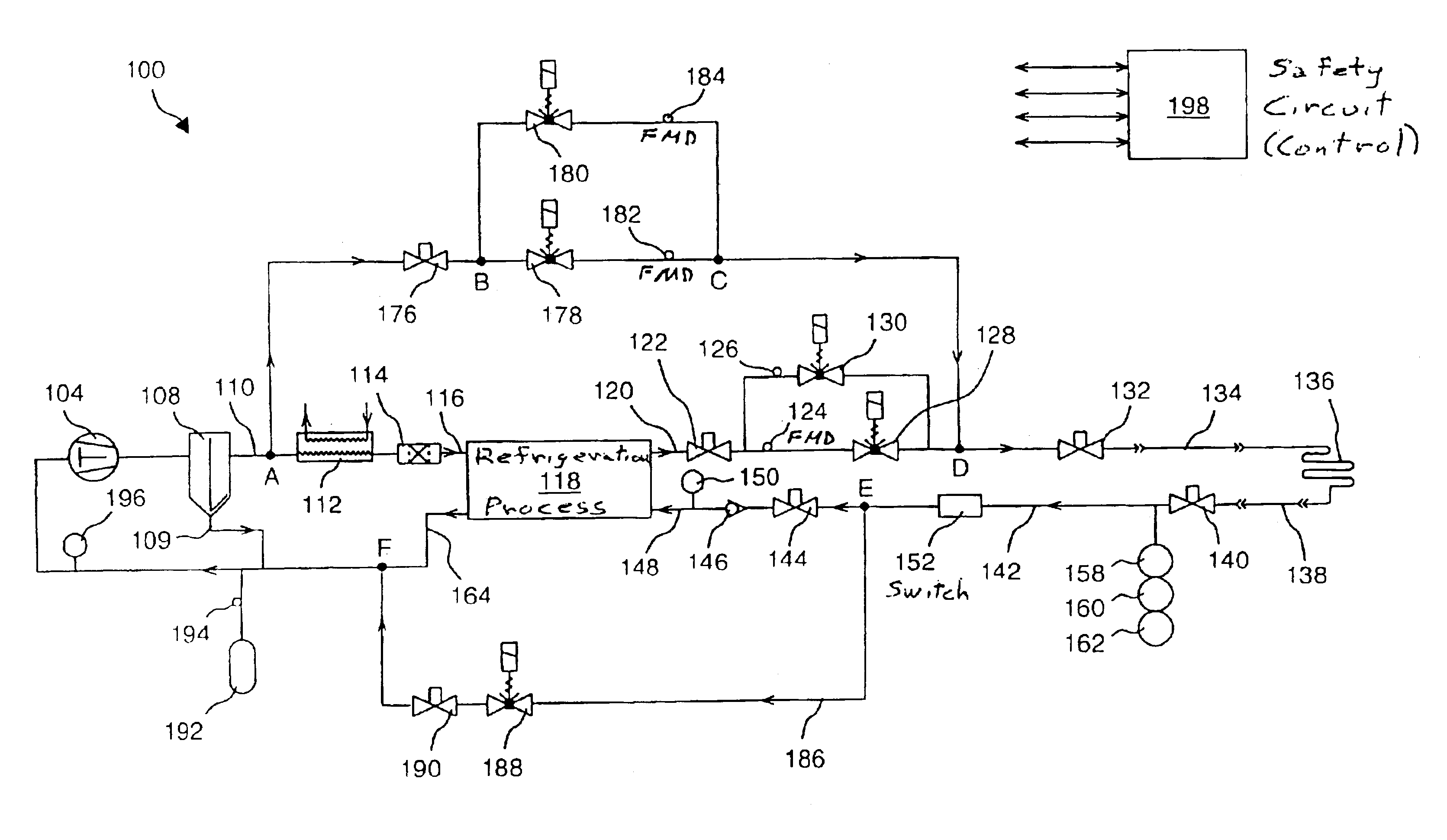
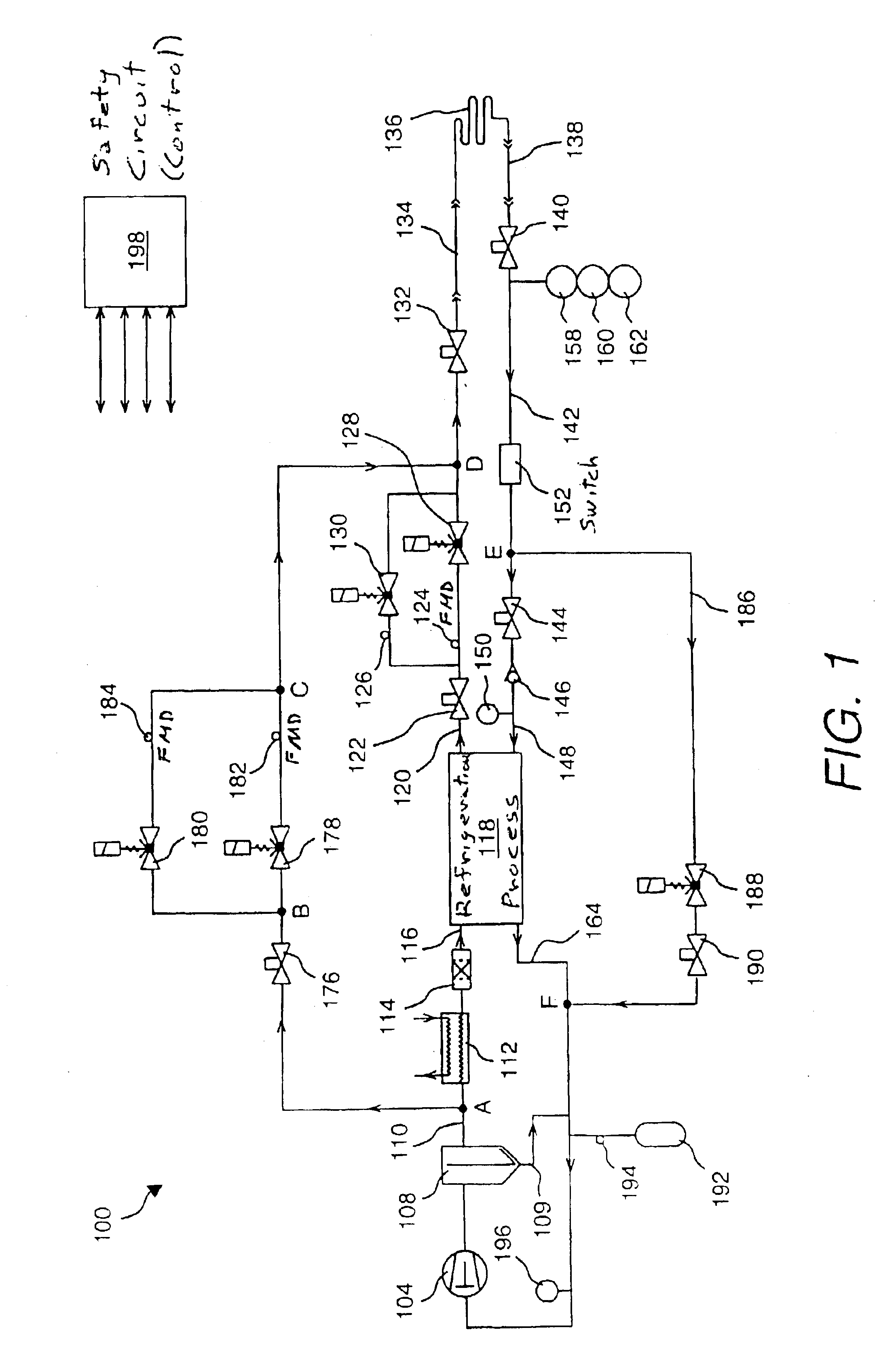
that follow in description indicate variations in accordance with the invention of refrigeration system 100 pertaining to the defrost bypass return function.

In a second embodiment (not shown), an additional heater or heat exchanger is placed (FIG. 1) in bypass line 186 between node E and bypass valve 188. This additional heater or heat exchanger provides further refrigerant temperature control such that the refrigerant temperature in bypass line 186 is prevented from being colder than the operating limits of bypass valve 188 and / or service valve 190. The heat exchanger could exchange heat with any other process flow, including cooling water. In the case of cooling water, it must be controlled such that the water does not freeze.

In a third embodiment (not shown), instead of using standard 2 position (open / closed) valves or proportional valves (FIG. 1) for bypass valve 188 and service valve 190, valves that are rated for cryogenic temperatures are used for bypass valve 188 and service...

sixth embodiment

FIG. 3 illustrates a sixth embodiment in accordance with the invention of the defrost return bypass loop of refrigeration system 300. In this embodiment, an array of return valves are present such that the defrost refrigerant flow is returned to one of several potential places in refrigeration process 118.

As an example, refrigeration system 300 of FIG. 3 includes a bypass valve 302, a bypass valve 304, and a bypass valve 306, the inlets of which are hydraulically connected to bypass line 186 connecting to node E along with bypass valve 188. The outlets of bypass valves 302, 304, and 306 are connected back into different points within refrigeration process 118 based on the return refrigerant temperature. Although they are not shown in FIG. 3, service valves may be inserted in line with bypass valves 302, 304, and 306. Those portions of the system not shown in FIG. 3 are similar to FIG. 1.

This arrangement of bypass valves 302, 304, and 306 allows return gas to be injected back into re...

embodiments 7 through 14

that follow indicate variations of refrigeration system 100 pertaining to the normal defrost supply function.

FIG. 4 (seventh embodiment) illustrates a variation of the defrost supply loop of refrigeration system 100. In this embodiment, refrigeration system 400 of FIG. 4 includes an additional heat exchanger 402, which is inserted in line between nodes C and D. Heat exchanger 402 is a conventional heat exchanger or heater.

In some applications, there is a need for the refrigerant feeding customer-installed evaporator coil 136 to be at a specific minimum elevated temperature. However, defrost valve 178, defrost valve 180, and their associated FMDs 182 and 184 cause the refrigerant temperature to drop, due to expanding gas. As a result, the temperature of the refrigerant feeding evaporator coil 136 drops, typically by about 10° C. To compensate, heat exchanger 402 is inserted between nodes C and D to reheat gas. If heat exchanger 402 has no controls: it simply exchanges heat between di...


PUM

PropertyMeasurementUnit
temperaturesaaaaaaaaaa
discharge pressuresaaaaaaaaaa
pressureaaaaaaaaaa

Abstract

Heating / defrost constructions of a very low temperature refrigeration system having a defrost supply circuit and a defrost return bypass circuit optimizing the heating / defrost cycle, preventing overload (excessive pressure) of its refrigeration process and protecting components from damaging temperatures. The defrost cycle operates continuously, when required, and provides a shorter recovery period between heating / defrost and cooling operating modes. The rate of the temperature change during cool down or warm up is controlled in an open loop fashion by controlled refrigerant flow in bypass circuits.

Description

FIELD OF THE INVENTIONThis invention is directed to heating / defrost cycles of a very low temperature refrigeration system, and more particularly, to an improved heating cycle incorporating a defrost supply loop and a defrost return bypass loop for optimizing the heating / defrost cycle, for preventing overload (excessive pressure) of its refrigeration process and thereby allowing the defrost cycle to operate continuously, for shorter recovery period between heating / defrost and cooling operating modes, for controlled flow where the rate of the temperature change during cool down or warm up is controlled in an open loop fashion.BACKGROUND OF THE INVENTIONRefrigeration systems have been in existence since the early 1900s, when reliable sealed refrigeration systems were developed. Since that time, improvements in refrigeration technology have proven their utility in both residential and industrial settings. In particular, low-temperature refrigeration systems currently provide essential i...

Claims


Application Information

Patent Timeline
Patent Type & Authority Patents(United States)
IPC IPC(8): C09K5/00C09K5/04F16K47/00F16K47/10F25B9/00F25B47/02F25B41/04F25B40/00G01P13/00F25B41/06
CPCC09K5/045G01P13/0066F16K47/10F25B9/006F25B40/00F25B41/043F25B47/022C09K2205/13C09K2205/22F25B9/00F25B41/04F25B41/06F25B2400/18F25B2500/06C09K2205/112F25B41/22F25B41/385F25B41/24
Inventor FLYNN, KEVIN P.
Owner EDWARDS VACUUM LLC
Why Eureka
Try Eureka