Imaging plate cassette for extended X-ray photographs

Inactive Publication Date: 2005-01-18
FUJIFILM MEDICAL SYST USA INC
View PDF12 Cites 16 Cited by
  • Summary
  • Abstract
  • Description
  • Claims
  • Application Information

AI Technical Summary

Benefits of technology

Another object of the present invention is to provide an extended X-ray film imaging plate

Problems solved by technology

The above described conventional X-ray film and film cassette, whether viewed as a typical x-ray photograph or digitized through computer radiography techniques, using storage phosphor imaging plates has a defect in that the film or visualizing element fitting within the cassette is generally not long enough to provide a full view of the spine (e.g. for scoliosis patients) or the other long bones of the body.
The sequential x-ray photographs of the prior art invariably left a small portion of the structure to be imaged off the x-ray photographs, leading to a gap in the diagnostic ability of x-ray procedures.
Meanwhile, though the more expensive MRI imagi

Method used


Image

  • Imaging plate cassette for extended X-ray photographs
  • Imaging plate cassette for extended X-ray photographs
  • Imaging plate cassette for extended X-ray photographs

Examples


Embodiment Construction

In FIGS. 1 to 5, an X-ray cassette 10 in accordance with an embodiment of the present invention is mainly for recording an X-ray image of the chest of a human body (not shown) on an X-ray film.

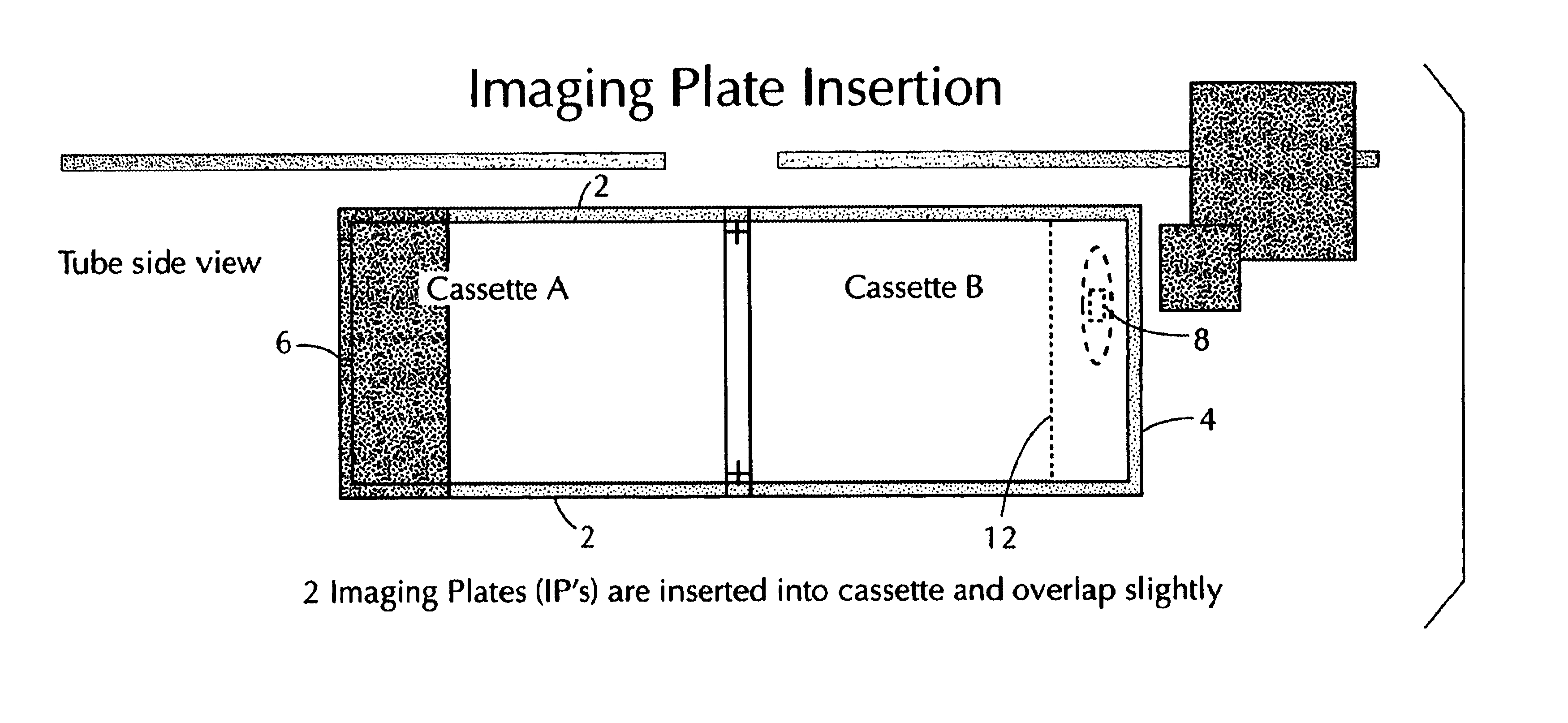
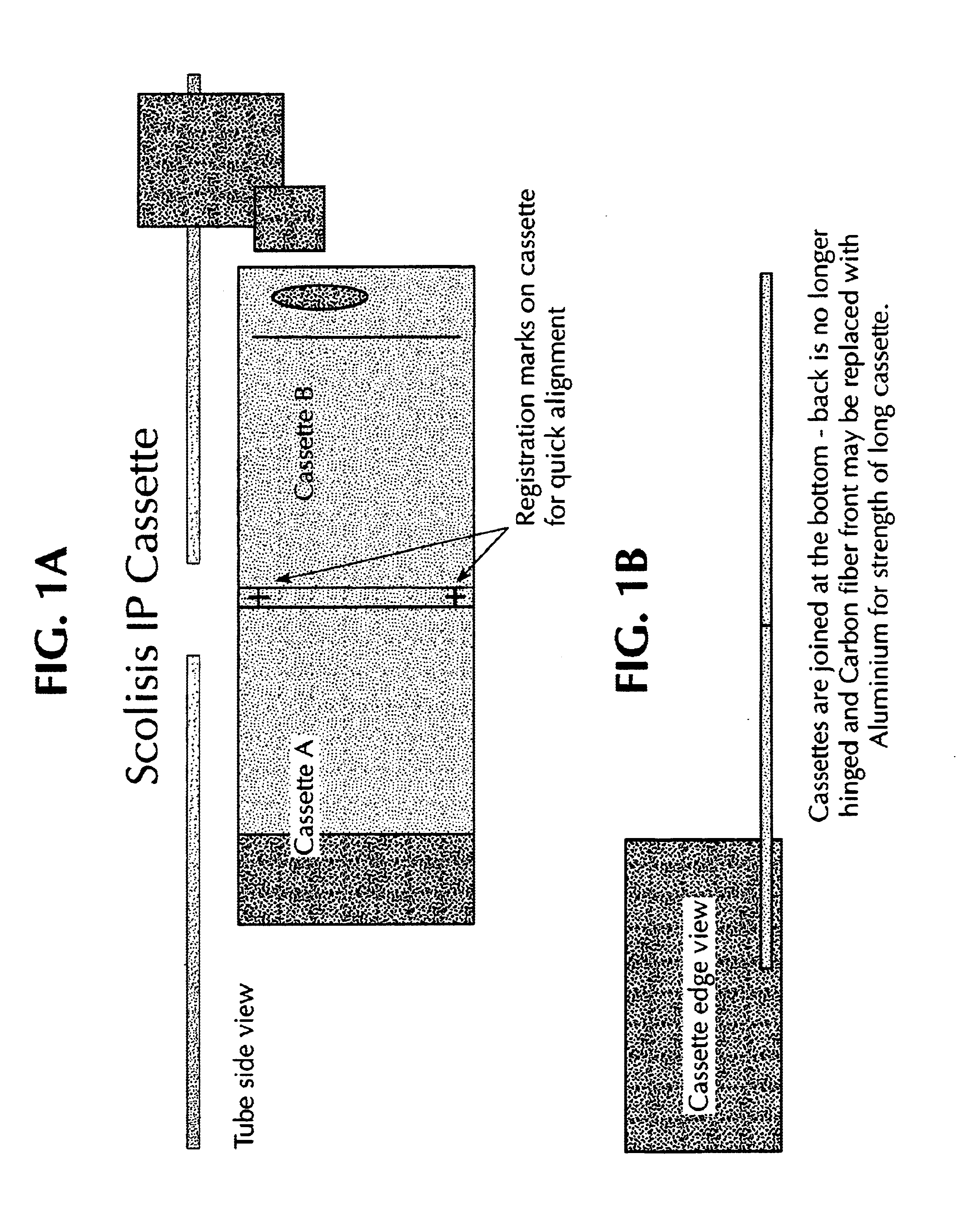
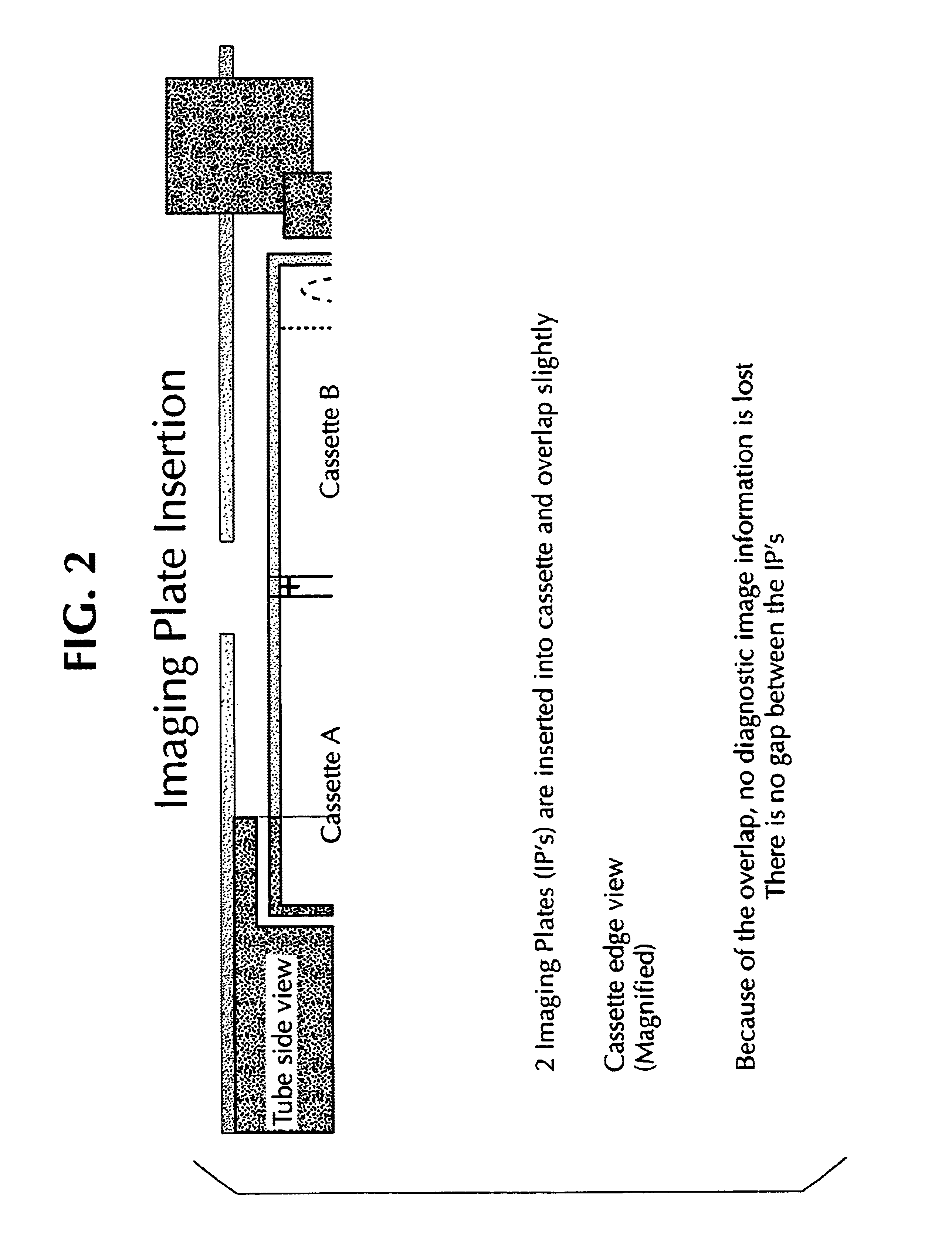
As shown in FIGS. 3A and 3b, for example, this invention volves an X-ray film cassette with a rectangular cartridge body having a front wall 4, a pair of side walls 2 and a back wall 6. A rectangular cover 14 is hinged at one side thereof to the back wall 6 of the body by hinge 12. A latch 8 is provided at one side of the cover 14 opposite to the hinged side, this latch 8 being manually operable to be moved from a latching position to a released position. A slot is provided in the front wall 4 of the body to engage the latch 8 of the cover 14, and at least two imaging plates 18 are provided for recording an image generated by an X-ray source. The imaging plates 18 are arranged in partial oven overlapping relation overlap so as to prevent a loss of diagnostic information.

The cassettes are joine...


PUM


Abstract

A method of taking an extended X-ray photograph by using an imaging plate or a computed radiography cassette devised to contain a longer digital X-ray image such that a longer complete image of a subject may be rendered such that no diagnostic information is lost in examinations of scoliosis or the long bones of the body. When the cassette is exposed to X-rays through an object, an X-ray transmission image of the object is recorded on a stimulable phosphor sheet and, at the same time, the X-ray film is exposed to light instantaneously emitted from the stimulable phosphor sheet upon exposure to X-rays to record an extended photographic latent image of the X-ray transmission image of the object on the X-ray film or a photostimulable phosphor sheet alone.

Description


Claims


Application Information

Patent Timeline
Owner FUJIFILM MEDICAL SYST USA INC
Why Eureka
Try Eureka