Filter with varying cell channels

a filter and cell channel technology, applied in the direction of filtration separation, machine/engine, separation process, etc., can solve the problem of increasing back pressure against the engine, and achieve the effect of improving the capacity for storing carbonaceous, good gas flow rate during use, and efficient and cost-effectiv

Inactive Publication Date: 2005-01-18
CORNING INC
View PDF24 Cites 77 Cited by
  • Summary
  • Abstract
  • Description
  • Claims
  • Application Information

AI Technical Summary

Benefits of technology

The present invention provides diesel particulate filters with increased capacity for storing carbonaceous soot and ash particulate while maintaining good ga

Problems solved by technology

This resistance to flow can be measured across the length of the fi

Method used


Image

  • Filter with varying cell channels
  • Filter with varying cell channels
  • Filter with varying cell channels

Examples


Embodiment Construction

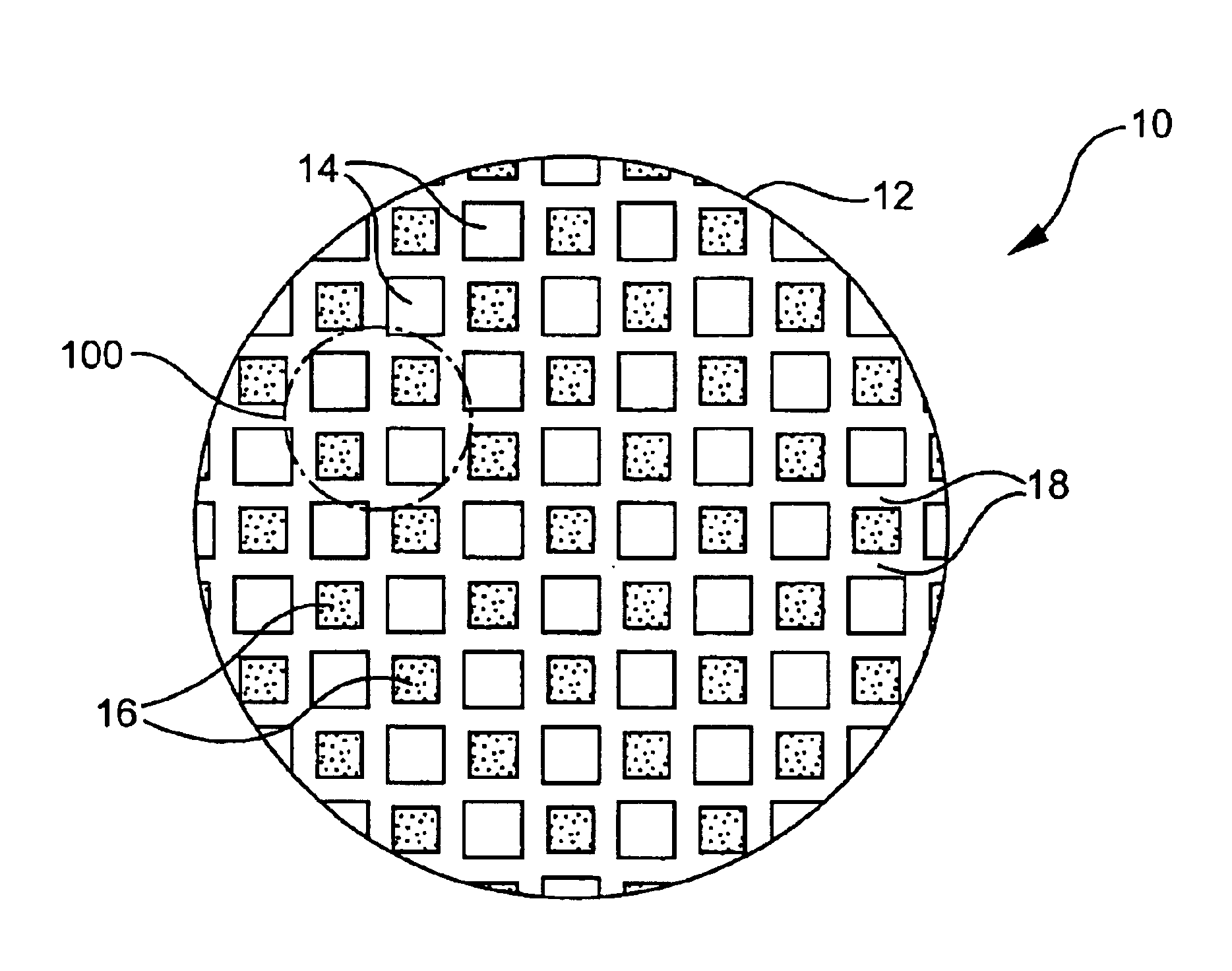
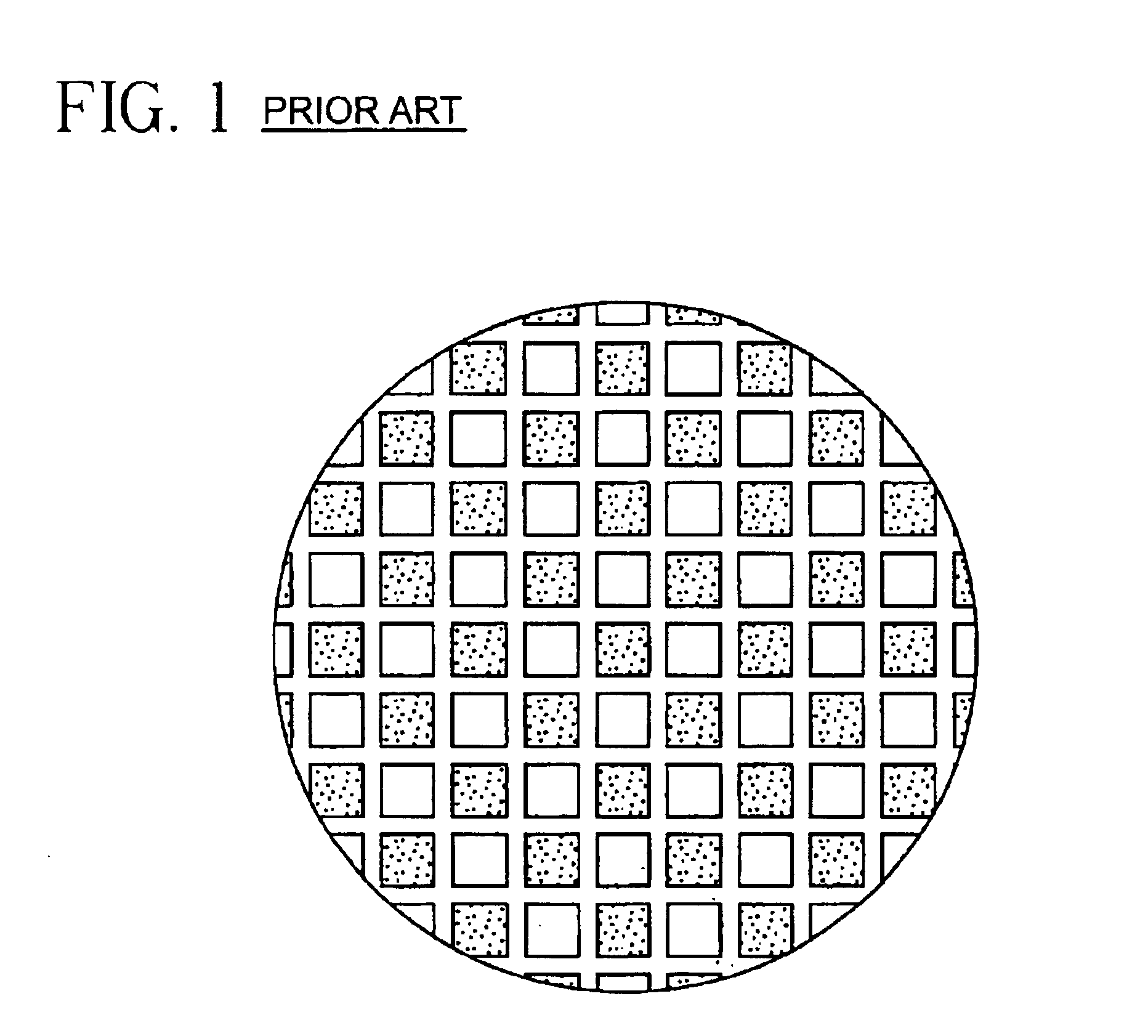
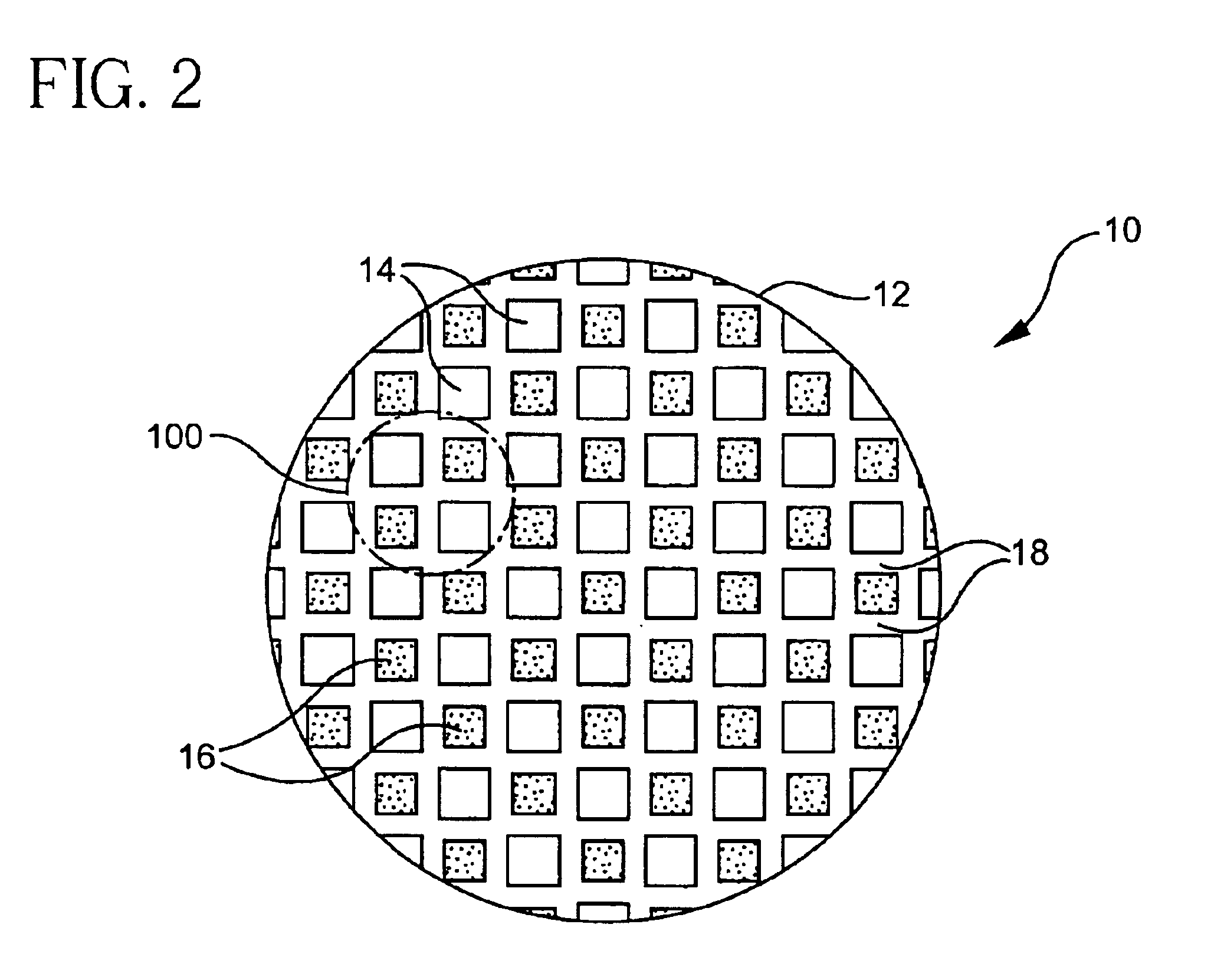
Referring to FIG. 1 therein illustrated is a top view of a prior art end-plugged honeycomb structure with cell channels of equal hydraulic diameter. A top view of an embodiment of the present invention is illustrated in FIG. 2. Honeycomb 10 has a front or inlet end 12. Although not shown, the outlet end is opposite the inlet end 12. A plurality of cell channels which are divided into inlet cell channels 14 and outlet cell channels 16 extend between the inlet and outlet ends. The cell channels have a square cross-section formed by interior porous walls 18. Interior walls 18 are straight, running substantially longitudinal and mutually parallel between the inlet and outlet ends of the structure. The cell channels or passages are arranged to alternate between inlet cell channels 14 and outlet cell channels 16, resulting in a pattern of alternating cell channel with small and large hydraulic diameters. Therefore, each inlet cell channel 14 is bordered on all sides by outlet cell channel...


PUM

PropertyMeasurementUnit
Diameteraaaaaaaaaa

Abstract

A honeycomb structure which includes an inlet end and an outlet end opposing each other and a plurality of cell channels extending along an axis from the inlet end to the outlet end, the cell channels having non-equal, square cross-sections, and an extrusion die for making the same.

Description

BACKGROUND OF THE INVENTIONThe present invention relates to a multicellular structure, such as a honeycomb, particularly for trapping and combusting diesel exhaust particulates.Wall-flow filters are used in the purification of diesel exhaust. Typically such diesel particulate filters are made of cordierite or silicon carbide and include a honeycomb body having thin interconnecting porous walls which form parallel cell channels of equal hydraulic diameter, longitudinally extending between the end faces of the structure. Alternating cells on one end face of the honeycomb are plugged with a ceramic filler material to form a “checkerboard” pattern. The pattern is reversed on the opposite side, so that the ends of each cell are blocked at only one end of the structure. When diesel exhaust enters the filter through one end face (i.e., inlet end), it is forced to pass through the porous walls in order to exit through the opposite end face (i.e., outlet end).For diesel particulate filtratio...

Claims


Application Information

Patent Timeline
IPC IPC(8): B01D39/20B01D46/24F01N3/022F01N3/02B01D46/00B28B3/26
CPCB01D39/2068B01D46/2429B01D46/247B23H9/00F01N3/022B01D46/0001Y10T428/24744B01D46/2425B01D46/2451B01D46/2466B01D2046/2481B01D2046/2496B23H2200/30F01N2330/06F01N2330/30Y02T10/20Y10S55/30Y10T428/24157Y10T428/24149Y10T428/131Y02T10/12B01D46/249B01D46/2498B01D46/2482B32B3/12
Inventor BEALL, DOUGLAS M.MARCHER, JOHNNY
Owner CORNING INC
Why Eureka
Try Eureka