Multistage immersion type membrane separator and high-concentration wastewater treatment facility using same

a technology of wastewater treatment facility and immersion type, which is applied in water/sewage treatment, solid separation, osmosis/dialysis, etc., can solve the problems of clogging of blowholes and diffuser pipes, uniform upstream, and filtration membranes, and achieve reliable crossflow production and efficient filtration operation.

Inactive Publication Date: 2005-01-18
KUBOTA LTD
View PDF13 Cites 28 Cited by
  • Summary
  • Abstract
  • Description
  • Claims
  • Application Information

AI Technical Summary

Benefits of technology

to overcome the foregoing problem by providing a multistage immersion type membrane separator capable of effecting a reliable production of crossflow and efficient filtration operation in such a construction of arranging plate-like membrane cart...

Problems solved by technology

This sludge is dried with air during air diffusion operation, and the dried sludge causes clogging of the blowholes and diffuser pipes.
Clogging of some blowholes of the air diffuser 6 makes the upstream non-uniform, and some of the filtration membranes 5 fail to sufficiently receive membrane surface flushing effect.
This increases the filtration resistance of the intra-...

Method used


Image

  • Multistage immersion type membrane separator and high-concentration wastewater treatment facility using same
  • Multistage immersion type membrane separator and high-concentration wastewater treatment facility using same
  • Multistage immersion type membrane separator and high-concentration wastewater treatment facility using same

Examples


first preferred embodiment

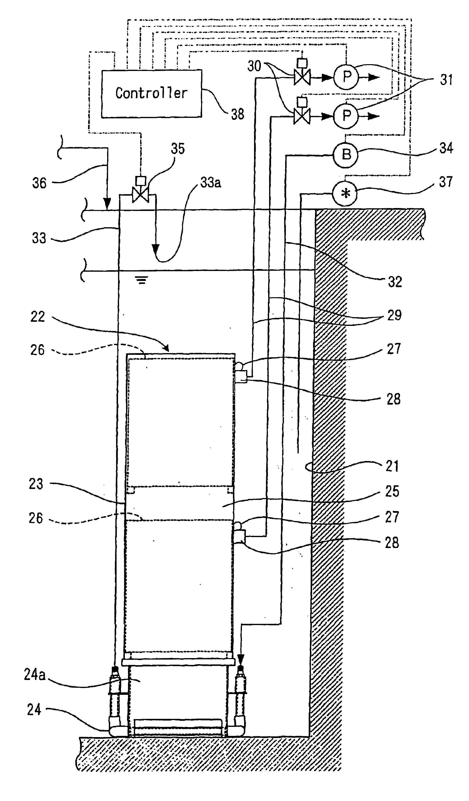
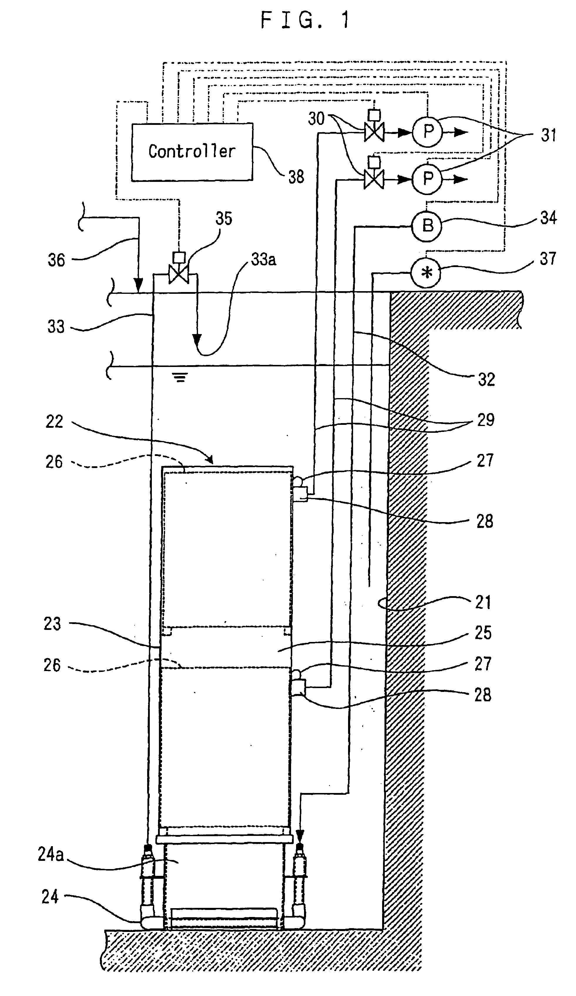
A first preferred embodiment will be described below based on FIGS. 1 to 5. Referring to FIG. 1, a treatment tank 21 is to biologically treat sewage water, waste water, etc, and a multistage immersion type membrane separator 22 is immersed therein. The membrane separator 22 has a filtration part 23 and an air diffuser 24 disposed below the filtration part 23. In the filtration part 23, a plurality of plate-like membrane cartridges 26 are disposed vertically in the interior of a casing 25 opening at its top and bottom. The membrane cartridges 26 are arranged in a vertical multistage fashion in which these are disposed in parallel and spaced at intervals for forming a crossflow passage having a predetermined width.

At every stage, an individual plate-like membrane cartridge 26 is connected to a collecting part 28 via a tube 27. A collecting means are formed by the collecting part 28, a suction pipe 29 connected to the collecting part 28, and a suction pump 31 connected to the suction p...

second preferred embodiment

A second preferred embodiment will be described based on FIGS. 6 and 7. This embodiment has the same basic configuration as the first preferred embodiment. Therefore, the same references have been used for similar parts which have the same functions as the first preferred embodiment, and their description is omitted. The followings are characteristic parts of the second preferred embodiment.

Referring to FIGS. 6 and 7, a filtration part 23 has an open space 48 between upper and lower sets of plate-like membrane cartridges 26. An inlet 50 making communication between the open space 48 and its surround intra-tank region 49 is disposed in a casing 25. The inlet 50 is spaced a predetermined length L apart from the bottom portions of the upper set of the plate-like membrane cartridge 26. A skirt 51 of the length L, which is part of the casing 25, surrounds a lower region of the upper set of the plate-like membrane cartridges 26.

With this construction, the intra-tank mixed liquor moves upw...

third preferred embodiment

A third preferred embodiment will be described based on FIG. 8. This embodiment has the same basic configuration as the first preferred embodiment. Therefore, the same references have been used for similar parts which have the same functions as the first preferred embodiment, and their description is omitted. The followings are characteristic parts of the third preferred embodiment.

Referring to FIG. 8, a filtration part 23 has a plurality of filtration units 52 that are arranged in a vertical multistage fashion. In each filtration unit 52, a membrane case 53 contains a plurality of plate-like membrane cartridges 26 that are disposed in parallel and spaced at intervals to form a passage having a predetermined width between the adjacent membrane surfaces. The filtration units 52 standing vertically are connected to each other via a connecting member 54.

With this construction, the upstream to be produced by the air lift action of the air blowing off from the blowholes 47 of the diffuse...


PUM

PropertyMeasurementUnit
Pressureaaaaaaaaaa
Diameteraaaaaaaaaa
Concentrationaaaaaaaaaa

Abstract

A multistage immersion type membrane separator in which an air diffuser is disposed under a filtration part immersed in a treatment tank, characterized in that: the filtration part has plural plate-like membrane cartridges arranged in a vertically parallel multistage fashion at spaced intervals for forming a crossflow passage of a predetermined width; and that the air diffuser has a diffuser tube disposed sidewardly that is communicated at its basal end to an air supply source and has at its lower side part plural blowholes, a flushing pipe that is communicated at its basal end to the tip of the diffuser tube and has at its tip an opening serving as an outlet above the diffuser tube, and a flushing valve disposed in the flushing pipe.

Description

TECHNICAL FIELDThe present invention relates to a multistage immersion type membrane separator and a high-concentration wastewater treatment facility using the same. More particularly, the invention relates to a membrane separation technique of performing wastewater treatment and sludge concentration by using a plate-like membrane cartridge, as well as a technique of performing activated sludge process of organic wastewater that is high in organic concentration and nitrogen concentration by using a multistage immersion type membrane separator.BACKGROUND ARTReferring to FIG. 33, in a conventional immersion type membrane separator 1, a casing 2 is made up of a membrane case 3 and diffuser case 4. In the membrane case 3, a plurality of plate-like membrane cartridges 5 are so arranged that their membrane surfaces stand vertically at predetermined spaced intervals (usually, 6 mm to 10 mm). An air diffuser 6 is disposed in the diffuser case 4. In the plate-like membrane cartridge 5, a fil...

Claims


Application Information

Patent Timeline
IPC IPC(8): B01D65/08B01D63/08B01D61/18B01F15/00B01D65/00B01F13/00B01F3/04B01F13/02C02F3/12C02F3/20C02F1/44C02F3/30B01F33/40
CPCB01D61/18C02F3/302B01D65/08B01F3/04248B01F3/04262B01F3/04985B01F13/025B01F15/00025C02F1/444C02F3/1273C02F3/20B01D63/082B01D2313/06B01D2321/2066B01F15/00123B01F2003/04148B01F2003/04319B01F2003/04361C02F3/12Y02W10/10B01F23/23113B01F23/23121B01F23/23123B01F23/231265B01F23/231231B01F23/29B01F33/40512B01F35/1452B01F35/20C02F3/06B01D63/0821
Inventor OKAJIMA, YASUNOBUUEJIMA, TATSUYANAGANO, MASAAKIIZUMI, KIYOSHIYAMADA, YUTAKAUESAKA, TAICHI
Owner KUBOTA LTD
Why Eureka
Try Eureka