Method and circuit for eliminating charge injection from transistor switches

a transistor switch and charge injection technology, applied in the field of transistor switch implementation, can solve the problem of the most serious limitation of transistor switches being the charge injection

Inactive Publication Date: 2005-01-18
CONCORDIA UNIVERSITY +1
View PDF4 Cites 0 Cited by
  • Summary
  • Abstract
  • Description
  • Claims
  • Application Information

AI Technical Summary

Benefits of technology

[0007]Accordingly, an object of the present invention is to elimi

Problems solved by technology

One of the most serious limitations of transi

Method used


Image

  • Method and circuit for eliminating charge injection from transistor switches
  • Method and circuit for eliminating charge injection from transistor switches
  • Method and circuit for eliminating charge injection from transistor switches

Examples


Embodiment Construction

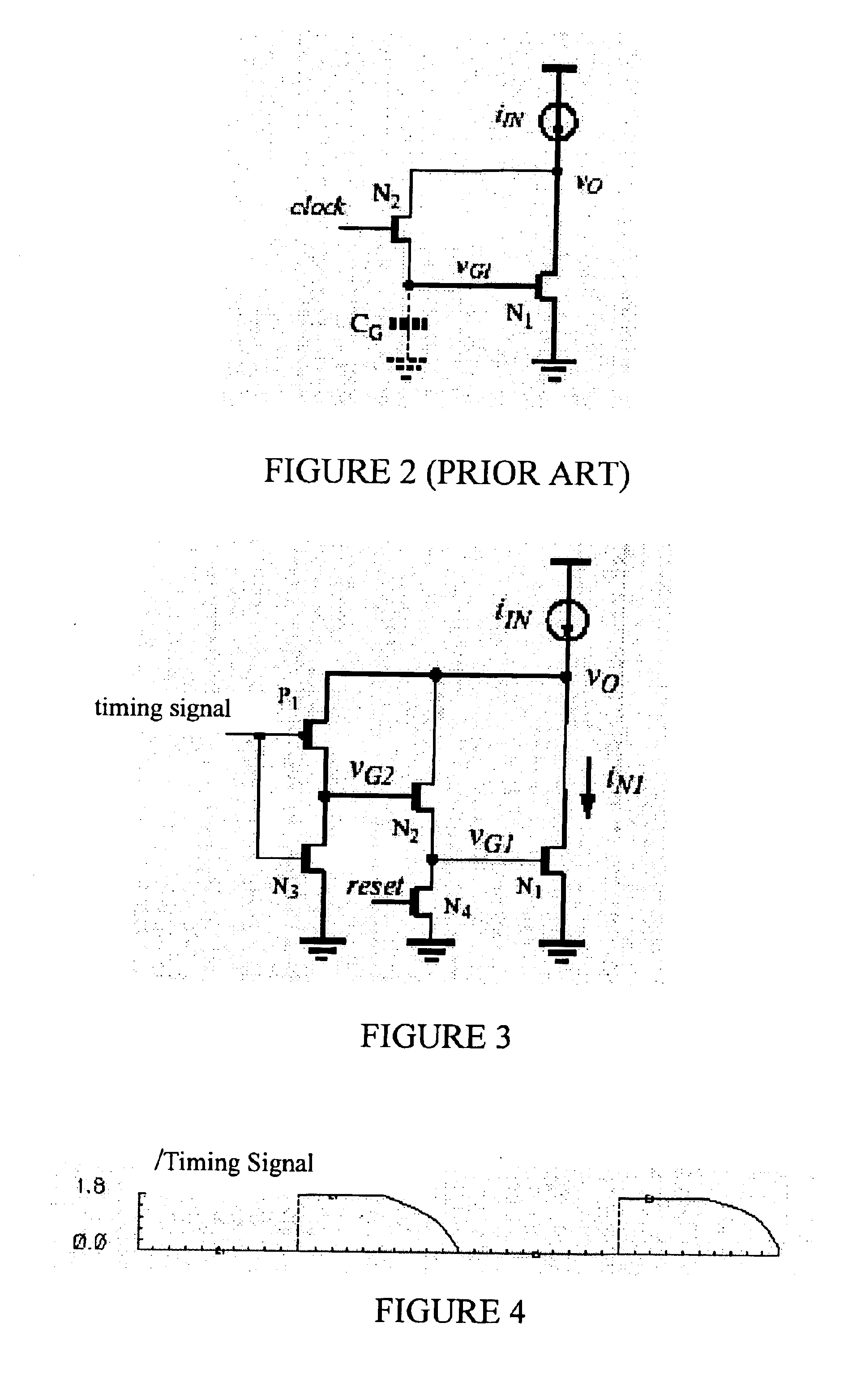
of a simulated waveform for the voltage at node VO from FIG. 3;

[0023]FIG. 5F is a graph of a simulated waveform for the current in transistor N1 from FIG. 3;

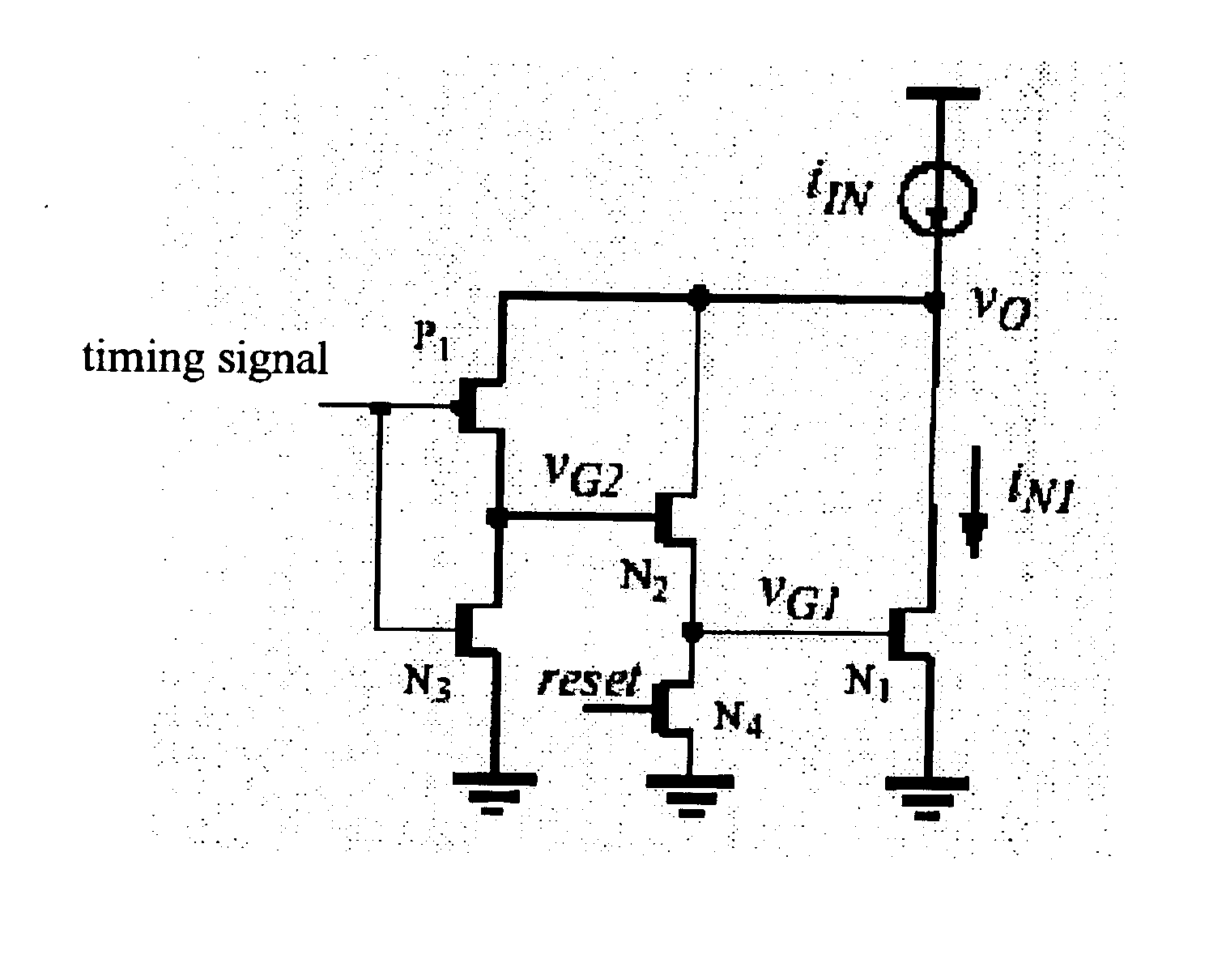
[0024]FIG. 6 is a graph of the voltage variation at the critical gate node of transistor N1 versus the input current of the circuit of FIG. 3; and

[0025]FIG. 7 is a graph of the gate voltage of the MOS switch N2 at the end of the first phase versus the input current of the circuit of FIG. 3.

DETAILED DESCRIPTION OF THE PREFERRED EMBODIMENT

[0026]Although the preferred embodiment consists of a MOSFET switch for the transistor, it can be appreciated that the technique can be used for JFETs as well.

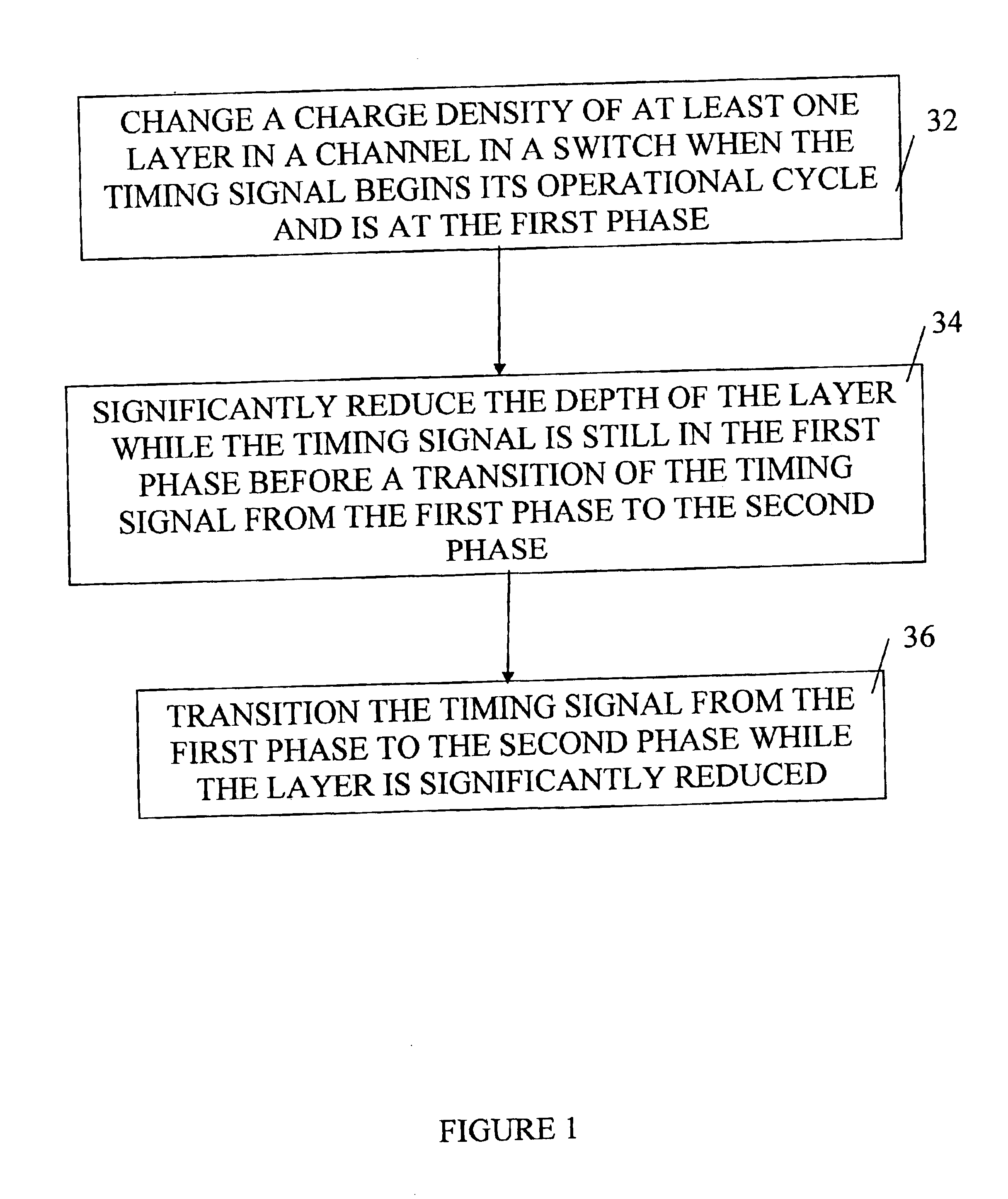
[0027]FIG. 1 is a flowchart of the method in accordance with the invention. It is a method for reducing charge injection from a field effect transistor switch in a circuit being controlled by a timing signal having an operation cycle comprising at least a first phase and a second phase. During phase 1, the timing signal is at a first voltag...


PUM


Abstract

A method for reducing charge injection from a field effect transistor switch in a circuit being controlled by a timing signal having an operation cycle with at least a first phase and a second phase. A charge density is changed in at least one layer in a channel in the switch when the timing signal begins its operational cycle and is in the first phase. A depth of the layer is significantly reduced while the timing signal is still in the first phase before a transition of the timing signal from the first phase to the second phase. The timing signal is transitioned from the first phase to the second phase while the layer is significantly reduced.

Description

FIELD OF THE INVENTION[0002]The invention relates to the implementation of transistor switches in various applications. More specifically, it relates to a method for eliminating charge injection from transistor switches when used in various types of circuits.BACKGROUND OF THE INVENTION[0003]Transistor switches find many applications in integrated-circuit design. In analog circuits, the switch is used to implement such useful functions as sample-hold.[0004]One of the most serious limitations of transistor switches is the charge injection effect. This is due to the charge released from the transistor channel, which is also called inversion layer beneath the gate, and injected into the connected drain and source nodes when the transistor is turned from on to off. Charge injection involves a complex process whose resulting effects depend upon a number of factors such as the dimension of the transistor, and the shape of the inversion layer in the gate area.[0005]A number of techniques ha...

Claims


Application Information

Patent Timeline
IPC IPC(8): G11C11/00H03K3/00G11C27/02
CPCG11C27/028
Inventor WANG, CHUNYAN
Owner CONCORDIA UNIVERSITY
Why Eureka
Try Eureka