LED drive circuit

a drive circuit and drive circuit technology, applied in the direction of pulse generators, pulse techniques, instruments, etc., can solve the problem that the display quality will be significantly affected by the hu

Active Publication Date: 2005-01-18
TEXAS INSTR INC
View PDF4 Cites 49 Cited by
  • Summary
  • Abstract
  • Description
  • Claims
  • Application Information

AI Technical Summary

Benefits of technology

An advantage of embodiments of the present invention is the influence of changes in temperature or power supply voltag...

Problems solved by technology

In particular, in a white LED, the change in...

Method used


Image

  • LED drive circuit
  • LED drive circuit
  • LED drive circuit

Examples


second embodiment

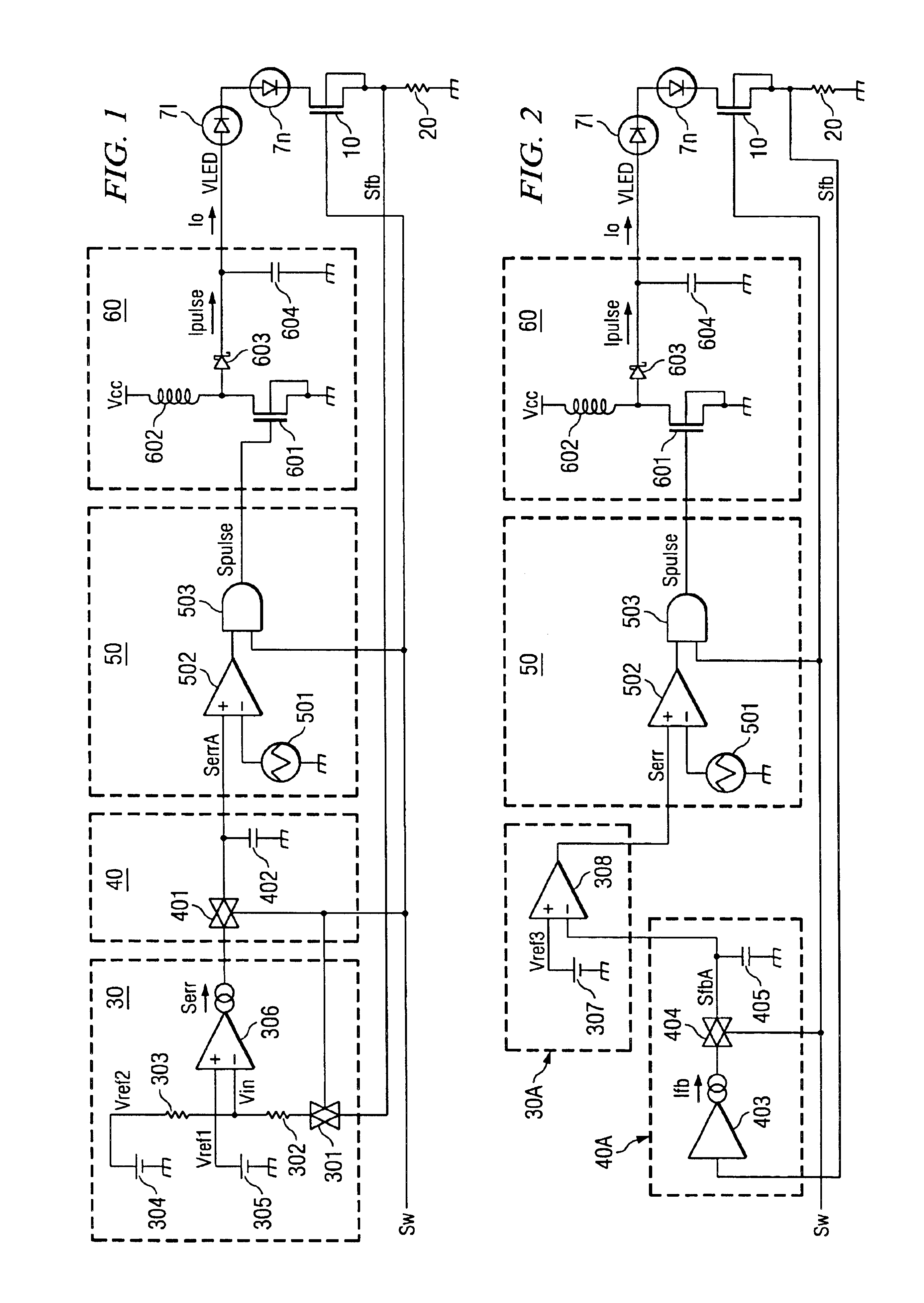
FIG. 2 is a block diagram illustrating an example of the configuration of the drive circuit disclosed in a second embodiment of the present invention. In FIGS. 1 and 2, the same symbols represent the same respective constituent elements.

In the drive circuit shown in FIG. 2, error signal generating unit 30 and signal holding unit 40 in the drive circuit shown in FIG. 1 are replaced with error signal generating unit 30A and signal holding unit 40A, respectively.

Error signal generating unit 30A includes reference voltage source 307 and differential amplifier 308. Signal holding unit 40A includes amplifier 403, transfer gate 404, capacitor 405. Error signal generating unit 30A is an embodiment of the error signal generating unit used in the present invention. Signal holding unit 40A is an embodiment of the signal holding unit used in the present invention. Amplifier 403 amplifies the detection signal Sfb as a voltage generated across resistor 20 to output a current corresponding to dete...

third embodiment

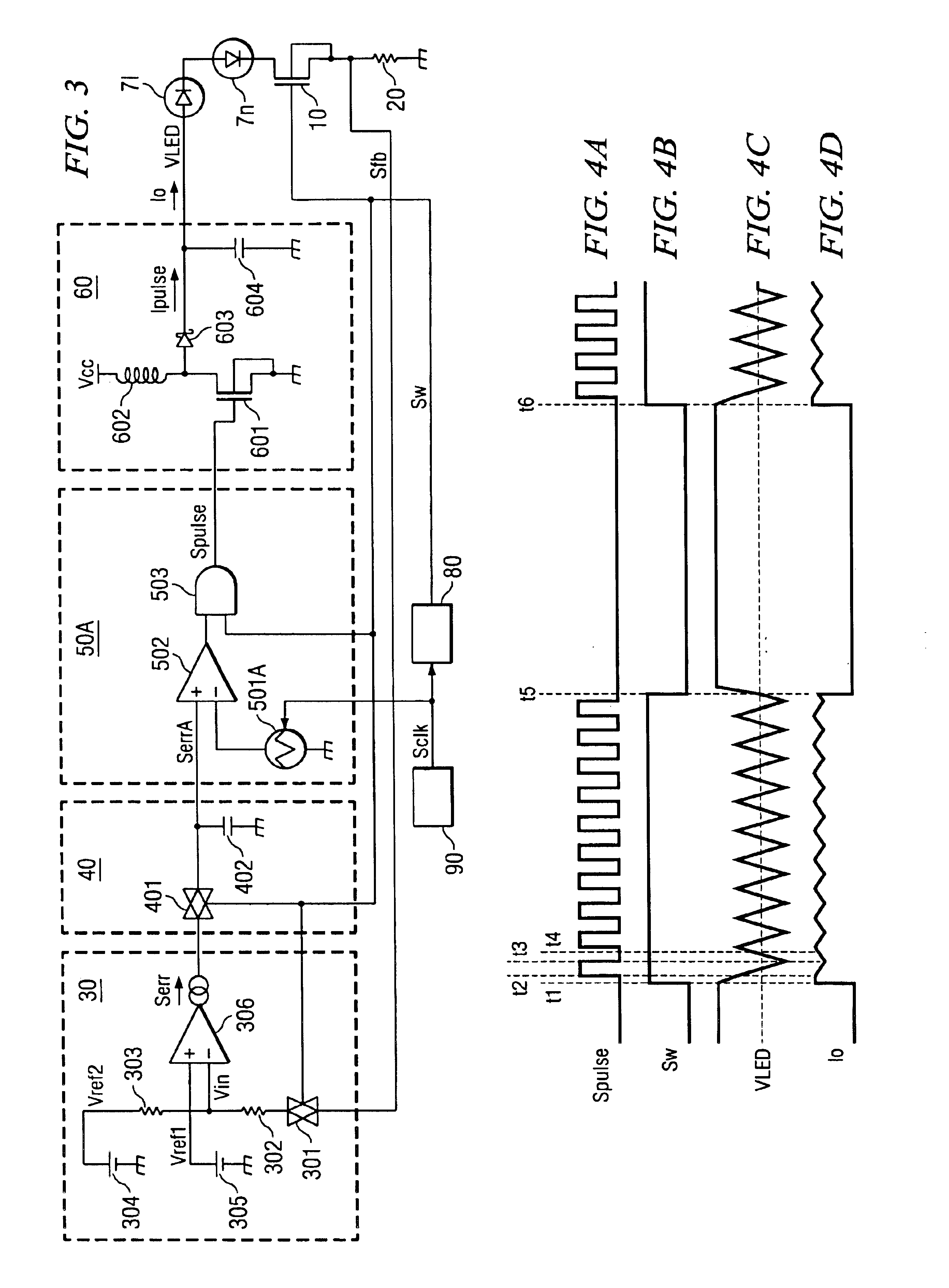
FIG. 3 is a block diagram illustrating an example of the configuration of the drive circuit disclosed in the third embodiment of the present invention. In FIGS. 1 and 3, the same symbols represent the same constituent elements, respectively.

In the drive circuit shown in FIG. 3, switching power supply control unit 50 in the drive circuit shown in FIG. 1 is replaced with switching power supply control unit 50A. Also, switch control unit 80 and clock signal generating unit 90 are added. The rest of the configuration of FIG. 3 is the same as the drive circuits shown in FIG. 1.

Switch control unit 80 is an embodiment of the switch control means used in the present invention.

Switching power supply control unit 50A operates switching power supply 60 in a switching period synchronously with clock signal Sclk generated by clock signal generating unit 90. Other functions are the same as those of switching power supply control unit 50 described above.

For example, as shown in FIG. 3, switching p...

fourth embodiment

FIG. 5 is a block diagram illustrating an example of the configuration of the drive circuit disclosed in a fourth embodiment of the present invention. The same symbols in FIGS. 2, 3, and 5 represent the same respective constituent elements.

In the drive circuit shown in FIG. 5, the switching power supply control unit 50 in the drive circuit shown in FIG. 2 is replaced with switching power supply control unit 50A. Also, switch control unit 80 and clock signal generating unit 90 are added. The rest of the configuration is the same as that of the drive circuits shown in FIGS. 2 and 5.

Like the drive circuit shown in FIG. 3, in the drive circuit shown in FIG. 5, the on / off state of n-type MOS transistor 10 is constantly switched at a prescribed phase, the noncontinuous change in the duty ratio can be restrained so that output current Io can be further stabilized.

The rest of the operation is the same as that of the drive circuit shown in FIG. 2, and the same effects can be realized.

Since t...


PUM


Abstract

A drive circuit for LEDs or other light-emitting elements with which the influence of the changes in temperature or power supply voltage and the element variations can be restrained in order to output a pulse current with a constant level. When n-type MOS transistor 10 is on, power is supplied from switching power supply 60 to the LED, and the current of LED is detected by resistor 20. The error signal Serr between said detection signal Sfb and setpoint signal Sref is generated by error signal generating unit 30 and is averaged by signal holding unit 40. The power supplied to the LED is controlled corresponding to the averaged error signal SerrA. When n-type MOS transistor 10 is turned off from the on state, the power supplied to the LED is stopped, and error signal SerrA is held in signal holding unit 40. When n-type MOS transistor 10 is turned on from the off state, the averaging of error signal Serr is started with the signal level of the held error signal SerrA used as the initial level.

Description

FIELD OF THE INVENTIONThe present invention pertains to a drive circuit, for example, a drive circuit for driving an LED (light-emitting diode) or other light-emitting elements.BACKGROUND OF THE INVENTIONLED or other light-emitting elements are usually used as the light source for backlight in a liquid-crystal display device. A light source for backlighting usually has a light intensity adjusting function (light adjusting function) in order to adjust the visibility or increase the power consumed by lighting. The light adjusting function is usually realized by the drive circuit for the light-emitting element.The simplest method of adjusting the amount of light emitted from an LED is to adjust the current flow to the LED. However, since the hue of the LED varies corresponding to the current, when the current is changed to adjust the amount of light, the hue of the LED also changes. In particular, in a white LED, the change in hue will significantly affect the display quality. Conseque...

Claims


Application Information

Patent Timeline
IPC IPC(8): H03K17/687H03K17/14H02M3/155H03K17/78
CPCH03K17/687H03K17/145
Inventor KOHARAGI, YOSHITAKANOGAWA, MASASHI
Owner TEXAS INSTR INC
Why Eureka
Try Eureka