
Amplifier device with a selectable active or passive operational mode and ultrasonic apparatus

Inactive Publication Date: 2005-01-18
SIEMENS HEALTHCARE GMBH
View PDF10 Cites 4 Cited by
  • Summary
  • Abstract
  • Description
  • Claims
  • Application Information

AI Technical Summary

Benefits of technology

It is possible to considerably reduce the power consumption, and therefore also the heat generation, of the amplifier arrangement, if the amplification element in the first signal path is only activated when the signal present at the first contact has a low signal amplitude and requires amplification. But in all other cases the amplification element can be deactivated, i.e. switched off. In that case no static currents flow in the amplification element and the power consumption goes down to zero. With an amplification element deactivated in this way, the signal at the first contact is still dependably transmitted to the second contact and is not blocked by the deactivated amplification element. A second signal path is provided which is switched parallel with the first signal path. In contrast to the first signal path, the second signal path does not contain any active circuit elements. It is passive and therefore does not result in any heating of the amplifier arrangement based on the energy supply.
The additionally provided second signal path allows a deactivation of the amplification element even if a signal is present at the first contact. Because of the lack of a signal transmission when the amplification element is deactivated, this would not be possible in a conventional amplifier arrangement without a second signal path. The passive operating mode, which is possible over wide phases, leads to a considerably reduced power consumption and heating of the amplifier arrangement. The integration capability is thereby improved.
Another embodiment is advantageous wherein a passive compensation element is provided in the second signal path intended for the first signal direction. In this case, the compensation element is used for an undesired compensating effect of the frequency response of the signal of the signal source at the first contact, which is to be amplified. In case of the employment of the amplifier arrangement in an ultrasound device, the signal source usually is a piezo-electric sound transducer. Its electrical equivalent diagram has as an essential component a parallel capacitive resistor at the output. With known amplifier arrangements, this parallel capacitive resistor is compensated by a parallel connected input inductive resistor connected at the first contact. In connection with the reception, the inductive resistor is not only effective for the low signal amplitudes, but is also effective in connection with the transmission. Since the transmitted signal has a very high signal amplitude, a saturation of the inductive resistor, which distorts the signal shape, may easily occur. To prevent this, such an inductive resistor is usually laid out with a very large structural volume. The integration capability becomes worse because of this. The inductive resistor which, with known amplifier arrangements, was switched parallel at the first contact, can be replaced by a corresponding compensation element in the second signal path. Since the second signal path is preferably intended for the first signal direction (e.g., the receiving direction), when the second compensation element is dimensioned, it is not necessary to take the high signal amplitudes occurring in the second signal direction (e.g., transmitting direction) into consideration. Thus it is possible to use a smaller structural volume without the danger of saturation occurring. This has a positive effect on the integration capability. The compensation element in the second signal path can be an inductive resistor, as well as a more elaborate reactive impedance, for example, a combination of several inductive resistors and capacitive resistors.

Problems solved by technology

Because of the lack of a signal transmission when the amplification element is deactivated, this would not be possible in a conventional amplifier arrangement without a second signal path.

Method used


Image

  • Amplifier device with a selectable active or passive operational mode and ultrasonic apparatus
  • Amplifier device with a selectable active or passive operational mode and ultrasonic apparatus
  • Amplifier device with a selectable active or passive operational mode and ultrasonic apparatus

Examples


Embodiment Construction

Corresponding parts have been provided with the same reference symbols in FIG. 1 to 4.

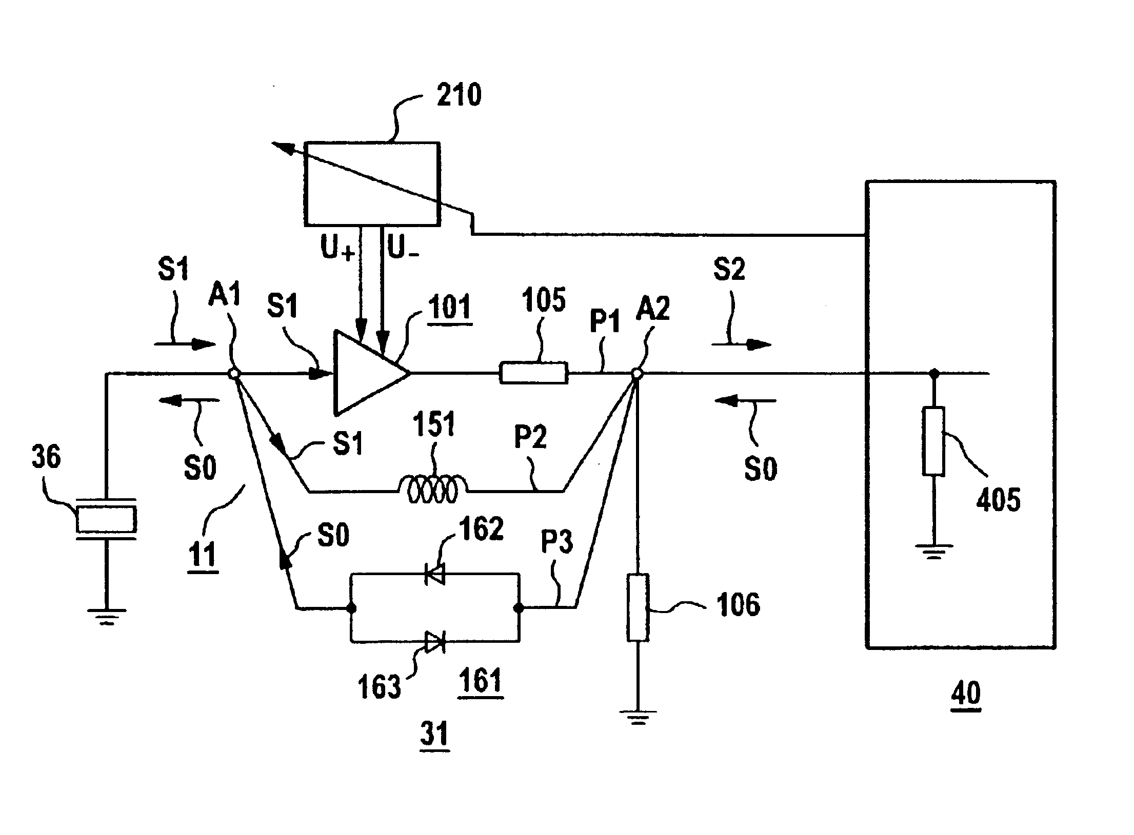
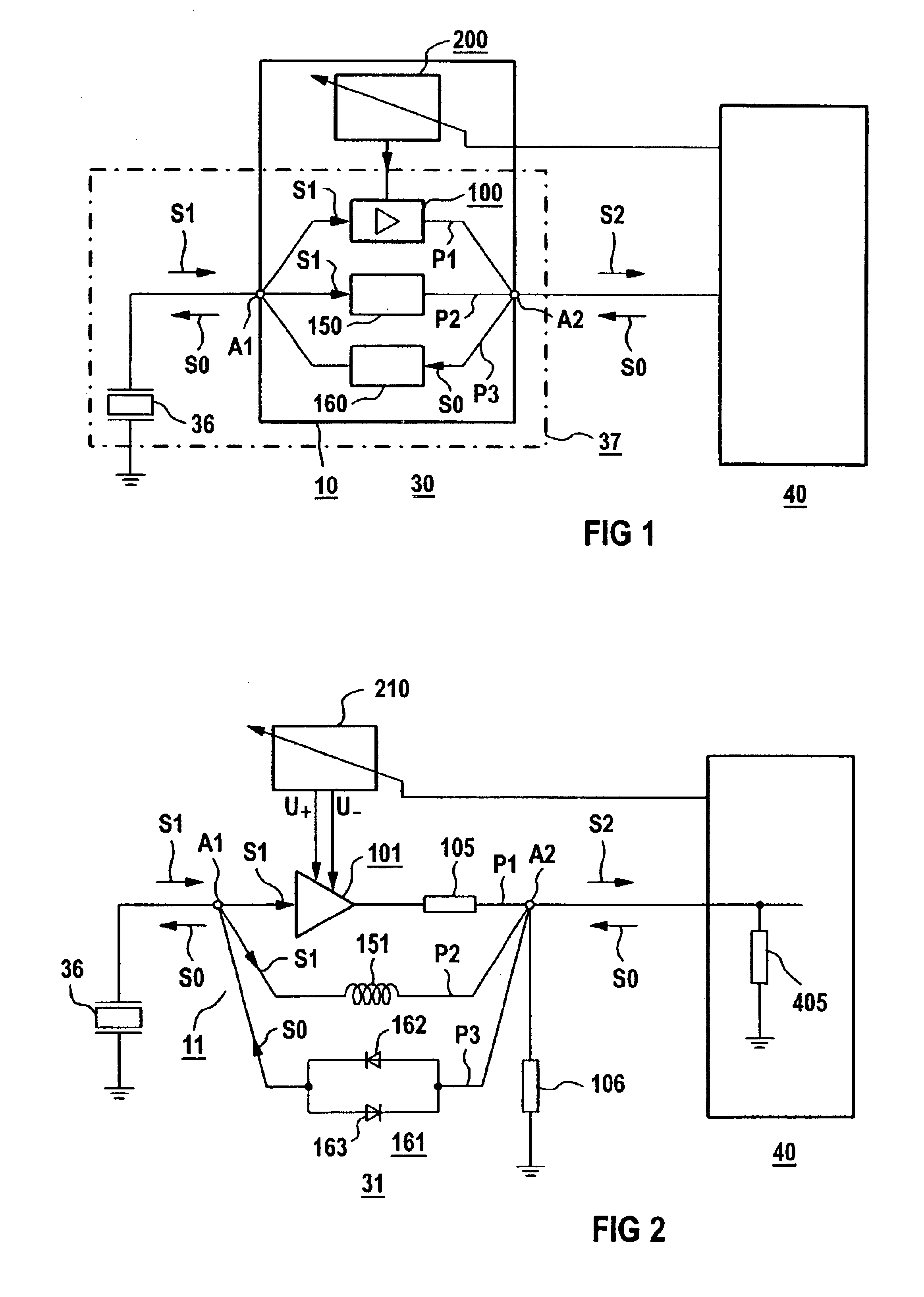
An ultrasound device 30, having an amplifier arrangement 10, a sound transducer 36 and a transmitter / receiver unit 40, is represented in FIG. 1. The sound transducer 36 is connected to ground on one side and is electrically connected with a contact A1 of the amplifier arrangement 10. A second contact A2 of the amplifier arrangement 10 is electrically connected via a connecting line, not represented in detail, with the transmitter / receiver unit 40. The amplifier arrangement 10 is comprised of a total of three signal paths P1, P2 and P3, which are intended for signal transmission between the two contacts A1 and A2. In particular, the first and the second signal path P1, or P2, are intended for the receiving direction, and the third signal path P3 for the transmitting direction. The division into different signal paths for the transmitting and receiving directions is primarily advantageous because the...


PUM


Abstract

An amplifier arrangement comprises an active amplification element arranged between a first and a second contact within a first signal path. A signal fed in at the first contact is amplified in the amplification element. Furthermore, a controller for a variably operation of the amplification element, as well as a passive second signal path. The second signal path, which is arranged parallel with the first signal path and bypasses the first signal path, is also contained therein. An ultrasound device contains such an amplifier arrangement.

Description

REFERENCE TO RELATED APPLICATIONSThe present patent document claims priority to German Application Serial No. DE 10208483.1, filed Feb. 27, 2002, which is hereby incorporated by reference.FIELD OF THE INVENTIONThe invention relates to an amplifier arrangement for amplifying a signal, comprising at least one active amplification element arranged between a first and a second contact within a first signal path, which amplifies a signal fed in at the first contact, and a controller for the variable operation of the amplification element. The invention further relates to an ultrasound device in which the amplifier arrangement is employed.BACKGROUNDAn amplifier arrangement is used in many technical devices. An example of this is a pulse-echo device in the form of a radar device, a sonar device or also of an ultrasound device. By means of such a pulse-echo device, a transmitted signal of a very high signal amplitude is radiated via an appropriately embodied transducer into a medium to be e...

Claims


Application Information

Patent Timeline
IPC IPC(8): H03F1/02H03F1/08H03F3/72H03F1/14H03F3/50H03F3/18
CPCH03F1/0266H03F1/14H03F3/72H03F3/50H03F2203/7239
Inventor OPPELT, RALPH
Owner SIEMENS HEALTHCARE GMBH
Features
  • Generate Ideas
  • Intellectual Property
  • Life Sciences
  • Materials
  • Tech Scout
  • Unparalleled Data Quality
  • Higher Quality Content
  • 60% Fewer Hallucinations
Learn More