Three level stacked reflective display

a liquid crystal display and reflective technology, applied in semiconductor devices, diodes, instruments, etc., can solve the problems of consuming a considerable amount of energy for back lighting and draining the battery of portable devices, and achieve the maximum reflectivity of ambient light, low cost, and easy manufacturing

Inactive Publication Date: 2005-01-18
AU OPTRONICS CORP
View PDF4 Cites 48 Cited by
  • Summary
  • Abstract
  • Description
  • Claims
  • Application Information

AI Technical Summary

Benefits of technology

In accordance with the present invention, a structure and fabrication technology for a reflective, ambient light, low cost display is described comprising a plurality of pixels laid out side by side with stacked color cells such as three levels on top of each other forming a pixel. Each stack of three color cells being driven by an array of TFT's positioned on the bottom layer. Each pixel comprises a light transmitting front dielectric window, three levels of individual cells RGB (Red, Green, and Blue) stacked on top of each other, each level having its own individual electrode, each electrode being connected by a vertical electrode running through another cell and having sealed conducting via holes running through each transparent dielectric window and being connected to an individual TFT. The bottom panel having a reflective surface so as to provide maximum reflectivity of the ambient light. Placed under the reflective surface is an array of TFT's which provide the electrical impulses necessary to set each individual potential in each vertically stacked cell with respect to a ground potential. A transmissive liquid crystal display can readily be fabricated by deleting the reflective surface.

Problems solved by technology

The back lighting consumes a considerable amount of energy and rapidly drains the battery of a portable device.
The most difficult part in building such a vertically stacked color cell reflective display is providing the vertical electrical connections between the electrodes at individual levels in each pixel and the respective TFT on the substrate below.

Method used


Image

  • Three level stacked reflective display
  • Three level stacked reflective display
  • Three level stacked reflective display

Examples


second embodiment

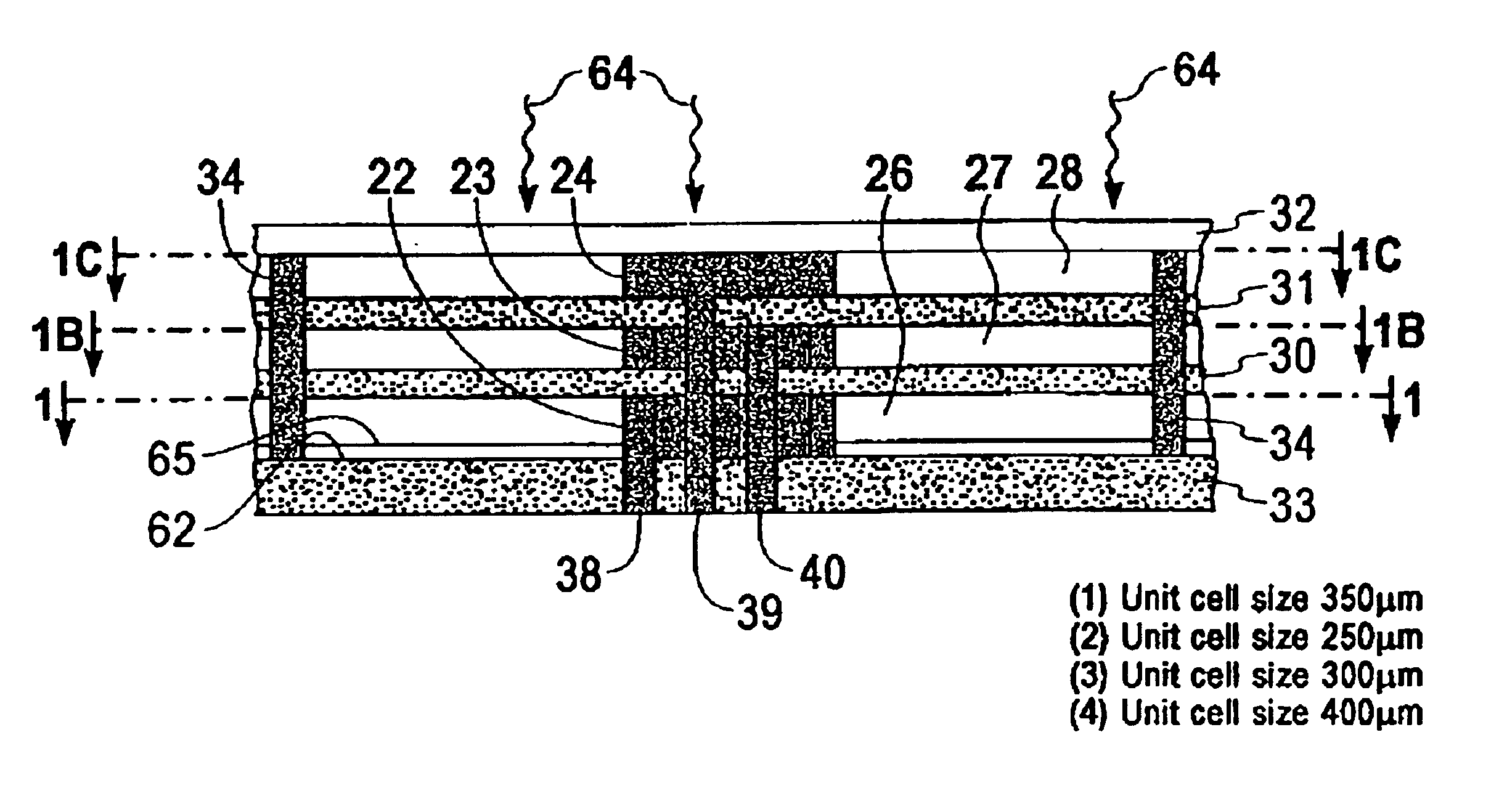
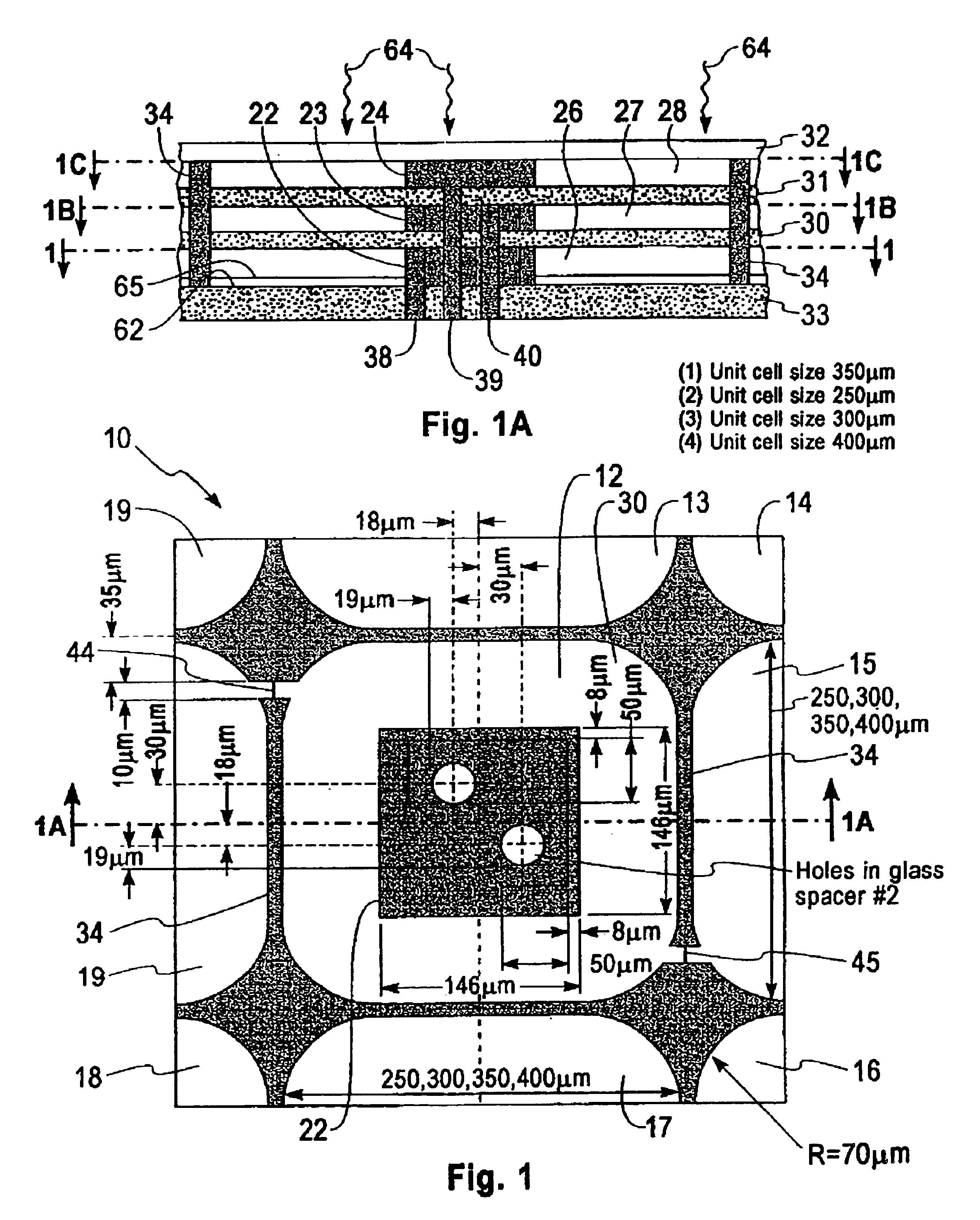
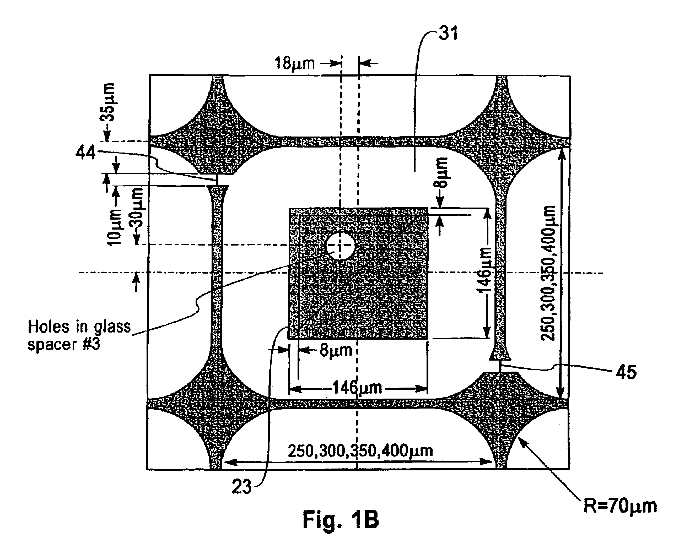
the invention is shown in FIG. 2. FIG. 2 shows a Guest-Host Liquid Crystal (LC) reflective or transmisive display 50. Reflective display 50 consists of a bottom layer 52 which carries the Thin Film Transistors (TFT's) (not shown). These transistors are fabricated by conventional means. The TFT bearing bottom layer has a dielectric insulator layer 54 on it. The dielectric insulator 54 has vias 56-58 which are filled with metal. Each metal via 56-58 is contacting a respective transistor which controls the potential on a respective level of the pixel. The metal is selected from the group of conductors such as Cu, Ni, Mo, Ag, Au, etc. The bottom layer 52 bearing the TFT's, the dielectric layer 54 and the metal filled vias 56-58 is planarized by a suitable means such as mechanical or chemical mechanical polishing (CMP).

In addition to the Guest-Host Liquid Crystal display described above, cholesteric LC reflective display and Holographic Polymer Dispersed LC (H-PDLC) reflective display ma...


PUM

PropertyMeasurementUnit
thickaaaaaaaaaa
temperatureaaaaaaaaaa
thicknessaaaaaaaaaa

Abstract

A structure and fabrication technology for a reflective, ambient light, low cost display is described incorporating a plurality of cells laid out side by side and stacked as many as three levels on top of each other. Each stack of three cells being driven by an array of TFT's positioned on the bottom layer. Each cell comprises a light transmitting front window, three levels of individual cells RGB (Red, Green, and Blue) stacked on top of each other, each level having its own individual electrode, each electrode being connected by vertical conducting via holes running through each transparent dielectric spacert and being connected to a individual TFT. The bottom panel having a reflective surface so as to provide maximum reflectivity of the ambient light. Placed under the reflective surface is an array of TFT's which provide the electrical impulses necessary to set each individual potential in each vertically stacked cell with respect to ground potential. A transmissive liquid crystal display can readily be fabricated by deleting the reflective surface. Also described are structures and assembly methods suitable for fabricating a Guest-Host LCD, a Cholesteric LCD, a Holographic Polymer Dispersed LCD and an Organic Light Emitting Diode (OLED) display.

Description

FIELD OF THE INVENTIONThis invention relates to reflective and transmissive liquid crystal displays, to electrophoretic displays and to Organic Light Emitting Diode (OLED) displays and more particularly, to an array of pixels where each pixel exists as three color cells stacked above one another driven by an array of thin film transistors positioned below the stacked color cells.BACKGROUND OF THE INVENTIONIn a typical liquid crystal (LC) display the three color cells: Red, Green and Blue (RGB) are placed side by side with respect to each other and are covered by a polarizer. The RGB color filter in LC displays use almost one third (⅓) of the incident light. To achieve high brightness and resolution the LC display requires back lighting. The back lighting consumes a considerable amount of energy and rapidly drains the battery of a portable device. The reflected ambient light display with individual color cells stacked on top of each other is capable of much higher pixel density per s...

Claims


Application Information

Patent Timeline
Patent Type & Authority Patents(United States)
IPC IPC(8): G02F1/01G02F1/13G02F1/1347G02F1/167G02F1/1362H01L27/32H01L27/28G02F1/1335G02F1/16756
CPCG02F1/1347G02F1/136227G02F1/167G02B26/001H01L27/3209G02B1/06G02F1/133553H01L27/3244G02F2201/16G02F1/16756H10K59/32H10K59/12
Inventor MATSUMOTO, KEIJIROMANKIW, LUBOMYR TARASSUEOKA, KUNIAKITAIRA, YOICHITAKEDA, KEIZOH
Owner AU OPTRONICS CORP
Why Eureka
Try Eureka