Rotary/fixed wing aircraft

a fixed-wing aircraft and rotor blade technology, which is applied in the field of hybrid aircraft, can solve the problems of stalling of the retreating rotor blade in high-speed forward flight, inability to provide control or lift to the aircraft, and failure to achieve the development of functional hybrid aircraft capable of carrying a plurality of passengers with a substantial payload, etc., and achieves rapid control, fast reaction time, and increased strength

Inactive Publication Date: 2005-01-25
PICA BRET D
View PDF10 Cites 20 Cited by
  • Summary
  • Abstract
  • Description
  • Claims
  • Application Information

AI Technical Summary

Benefits of technology

It is a further object of this invention to provide a rotor system capable of transitional flight over a range of airspeeds, thereby giving the pilot or flight crew more options.
It is a further object of this invention to provide a rotor system mounted as a modification to existing helicopter designs or retrofitted on existing helicopters to enhance the economic viability of incorporating the invention.
The present invention achieves these objectives by preferably incorporating an annular wing in conjunction with adjustable rotor blades. An aircraft equipped with the preferred embodiments of the present invention will lift off from the ground with the operating characteristics of a rotary wing aircraft in helicopter mode. When high speed flight is desired the aircraft accelerates above a low transitional mode speed limit, the rotor system is disengaged, rotor blade rotational motion is stopped, and the rotor blades are secured in a fixed configuration for fixed wing mode. Lift is substantially transferred from the rotor blades to the annular wing during the transition mode. Rotor blade flaps are employed in a unique and novel manner to facilitate control during helicopter, transitional and fixed wing modes.
However, because the annular wing and rotor blades effectively comprise the rotor disk, the annular wing's aerodynamic characteristics must be considered at moderate speeds where transition will occur to fixed wing mode. The annular wing has an angle of attack that describes the angle between its pitch and the relative wind. When the rotor disk tilts to provide horizontal motion the annular wings the angle of attack changes and may become disadvantageous. An airfoil typically achieves zero lift at an angle of attack negative to its chord line. This angle must be considered in the design of the annular wing and also the flight control system to limit adverse effects of negative lift of the annular wing versus the positive lift of the rotor blades as the airspeed increases.
Control systems are transferred from the swashplate system to the preferred piezoelectric actuators during transitional mode. After sufficient forward speed is obtained for the annular wing to provide lift, locking mechanisms engage from the rotor blades at their roots and interlock with the rotating hub. At the same instant, locking mechanisms engage from the rotor tips and interlock with the annular wing. The rotor blades can then be used in conjunction with die internal spars to transmit structural loads from the annular wing to the hub. This advantageously provides additional strength during high speed flight. Because the rotor blades cannot rotate about the longitudinal axis, the swashplate no longer provides flight control. An onboard computer transfers control to piezoelectric actuators on both leading and trailing edges of the rotor blades. Piezoelectric actuators are preferred due to their fast reaction times, and have been proven in a technology demonstrator. [See “Solid State Rotor Tested”, Aviation Week and attached to my provisional application, Ser. No. 60 / 386,031, which is incorporated herein by this reference.] Aircraft propulsion is then transferred to a horizontal thrust producing engine which provides thrust substantially parallel to the longitudinal axis of the aircraft and maintains the forward velocity of the aircraft. The rotating rotor system is then disengaged from its power source. Said rotor system then undergoes angular deceleration with the assistance of a brake connected to the shaft system. As the rotor blades angular velocity slows the airspeed relative to the retreating blade will approach zero and reverse. When the relative airspeed is near zero the rotor flap will become ineffective and its direction of movement will effectively reverse as the airspeed reverses relative to typical helicopter rotation. The piezoelectric flaps are employed to provide rapid control during this transition. Use of the shaft brake will minimize the period when the retreating blade flap is ineffective. When the rotor system ceases to rotate, locking détentes, for example, correctly position the rotor wings for airplane mode. A blade locking system then engages at each of the swashplate linkages so that airplane flight loads will not be transmitted directly through the swashplate. The aircraft is then in airplane mode. Rotor blade locking and rotor blade pitch locking are described by Nyhus in U.S. Pat. Nos. 6,161,799 and 6,170,779 which are incorporated herein by this reference.

Problems solved by technology

A functional, preferably single rotor, hybrid aircraft capable of carrying a plurality of passengers with a substantial payload has not been successfully developed.
The primary barrier to high speed helicopter flight is that the retreating rotor blade in high speed forward flight will stall because its effective airspeed approaches zero at a set rotational velocity.
There will be a period of time when the retreating rotor blade cannot provide any control or lift to the aircraft because of its near zero relative airspeed.
Therefore, a larger surface area during rotational flight is detrimental to efficiency and control responsiveness.
The annulus is attached to the aircraft and acts as a fixed wing and does not provide for rotation of the wing.
This configuration is not suited for rotation due to the eccentricity of the shape and corresponding asymmetrical moment of inertia.
This mechanism was investigated throughout the 1980's, but was not commercially introduced, possibly due the complexity and cost issues of the test program.
A particularly challenging issue in this design is the forward swept nature of the aft rotor blades which act as a primary lifting surface in forward, fixed-wing flight.

Method used


Image

  • Rotary/fixed wing aircraft
  • Rotary/fixed wing aircraft
  • Rotary/fixed wing aircraft

Examples


Embodiment Construction

The drawing figures are intended to illustrate the general manner of design and construction of the invention, and are not to scale. References, in the description and in the claims, to left, right, front, back and the like are used for descriptive purposes, and should not be misinterpreted as to limit the scope of the claims or invention. It shall be understood that the embodiment of the invention as described is capable of operation in other orientations than described or shown.

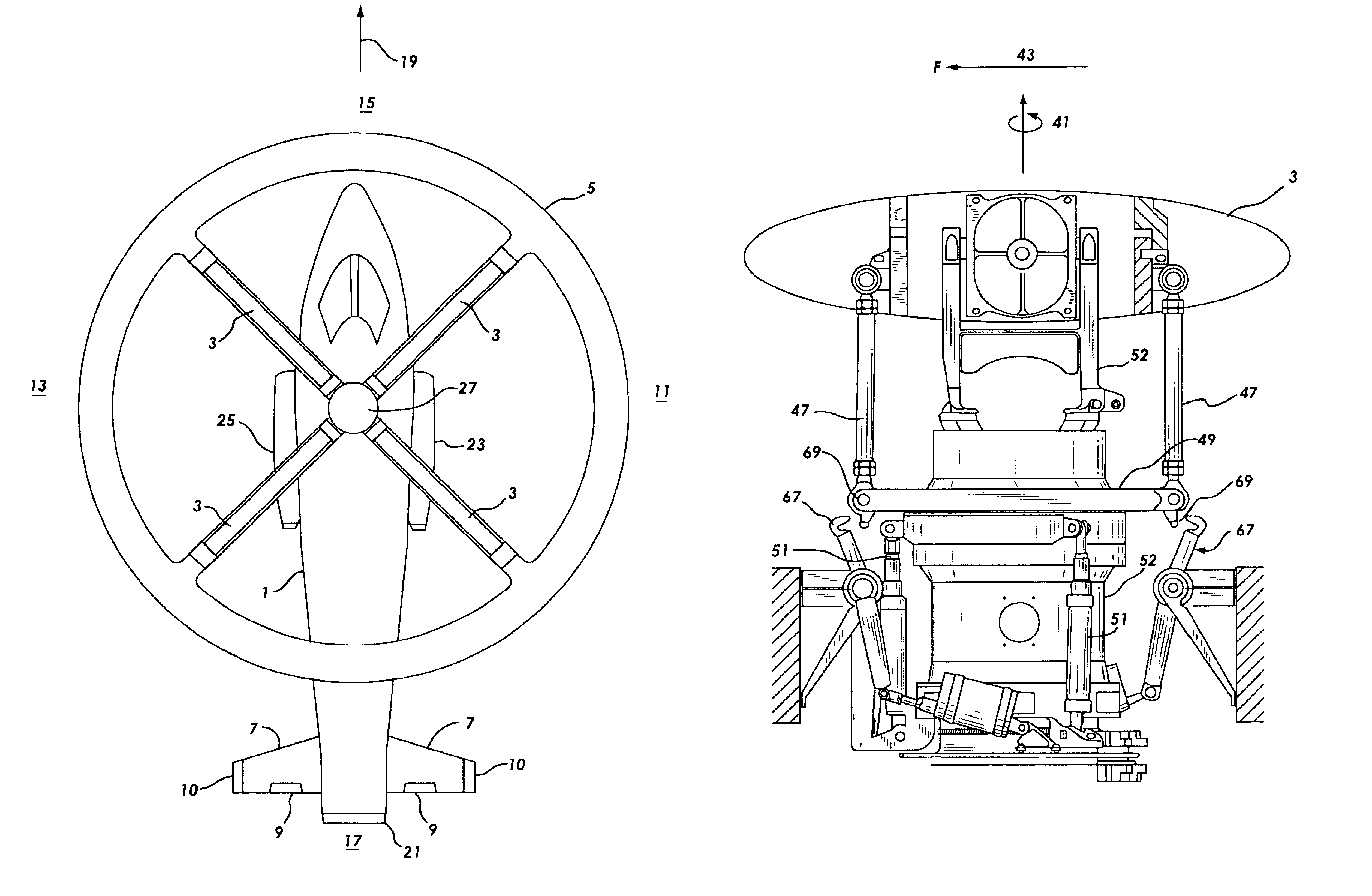
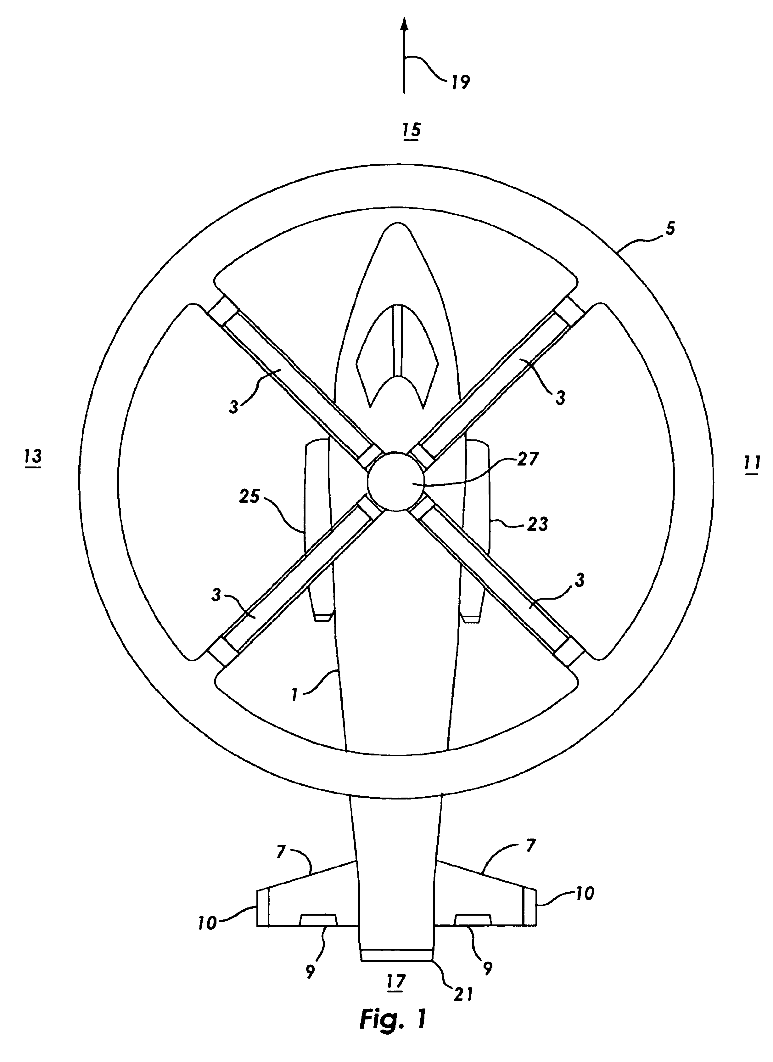
FIG. 1 illustrates an aircraft fuselage 1 equipped with an embodiment of the present invention comprised of rotor blades 3 of which any single rotor blade extends from rotating hub 27 to an annular wing 5. A horizontal stabilizer 7, elevators 9, and vertical stabilizers 10 on the fuselage 1 are common fixed wing aircraft embodiments. Aircraft directional references are right 11, left 13, nose 15, and tail 17. A longitudinal axis 19 extends lengthwise through the fuselage 1. A fan tail 21 or vectoring thrust...


PUM


Abstract

A rotor system that allows an aircraft to operate as a helicopter and as an airplane is disclosed. The invention incorporates an annular airfoil attached at the tips of the rotor blades. The rotor system stops and is secured from rotation for operation at high forward speeds. The annulus acts as the primary lifting surface in airplane mode at high speed. The rotor blades incorporate leading and trailing edge flaps for control in transitional and fixed wing flight modes.

Description

BACKGROUND OF THE INVENTION1. Field of the InventionThe present invention relates to hybrid aircraft capable of operating as a rotary wing aircraft and as a fixed wing aircraft.2. Background of the InventionA functional, preferably single rotor, hybrid aircraft capable of carrying a plurality of passengers with a substantial payload has not been successfully developed. The military, commercial and private benefits of a vehicle that can take off vertically, transition from low to high speed forward flight and back to low speed flight for vertical landing are well known.Vibration, structural and aerodynamic barriers presently practically prevent the use of high speed rotary wings. The primary barrier to high speed helicopter flight is that the retreating rotor blade in high speed forward flight will stall because its effective airspeed approaches zero at a set rotational velocity. Conversely, the advancing rotor blade sees a higher airspeed. Because lift vanes as the square of airspee...

Claims


Application Information

Patent Timeline
Patent Type & Authority Patents(United States)
IPC IPC(8): B64C27/32B64C27/00B64C27/22
CPCB64C27/32B64C27/22
Inventor PICA, BRET D.
Owner PICA BRET D
Why Eureka
Try Eureka