

Electric heating arrangement
a technology of heating arrangement and heating element, which is applied in the direction of electric heating, resistors, electrical apparatus, etc., can solve the problems of rapid degradation of thermal coupling efficiency, inconvenient heating arrangement, and progressively degraded thermal coupling of ptc heating element to the housing over time, so as to facilitate the attachment of plastic caps and achieve good thermally conductive contact , the effect of optimum thermal coupling
- Summary
- Abstract
- Description
- Claims
- Application Information
AI Technical Summary
Benefits of technology
Problems solved by technology
Method used
Image

Examples
Embodiment Construction
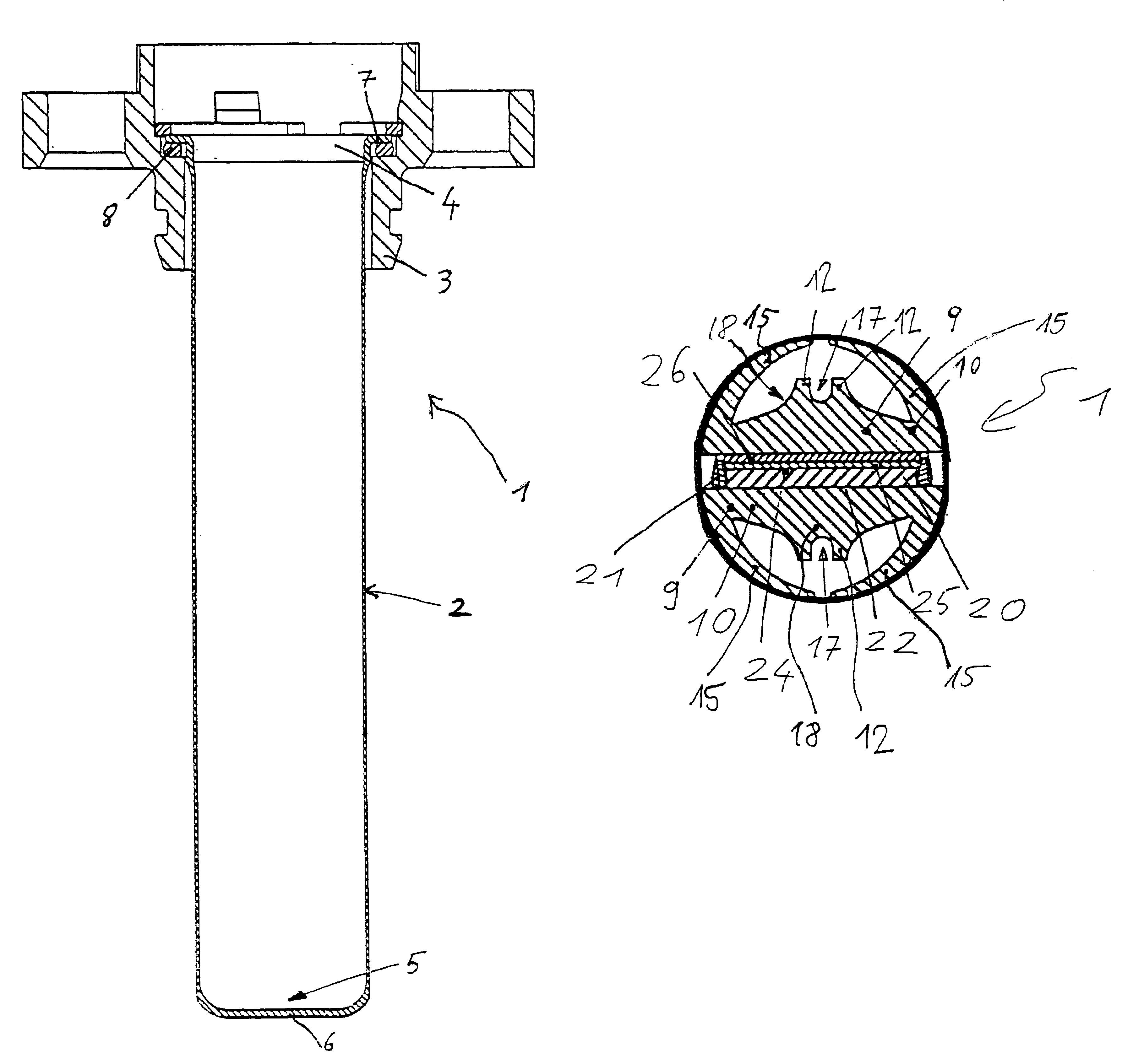
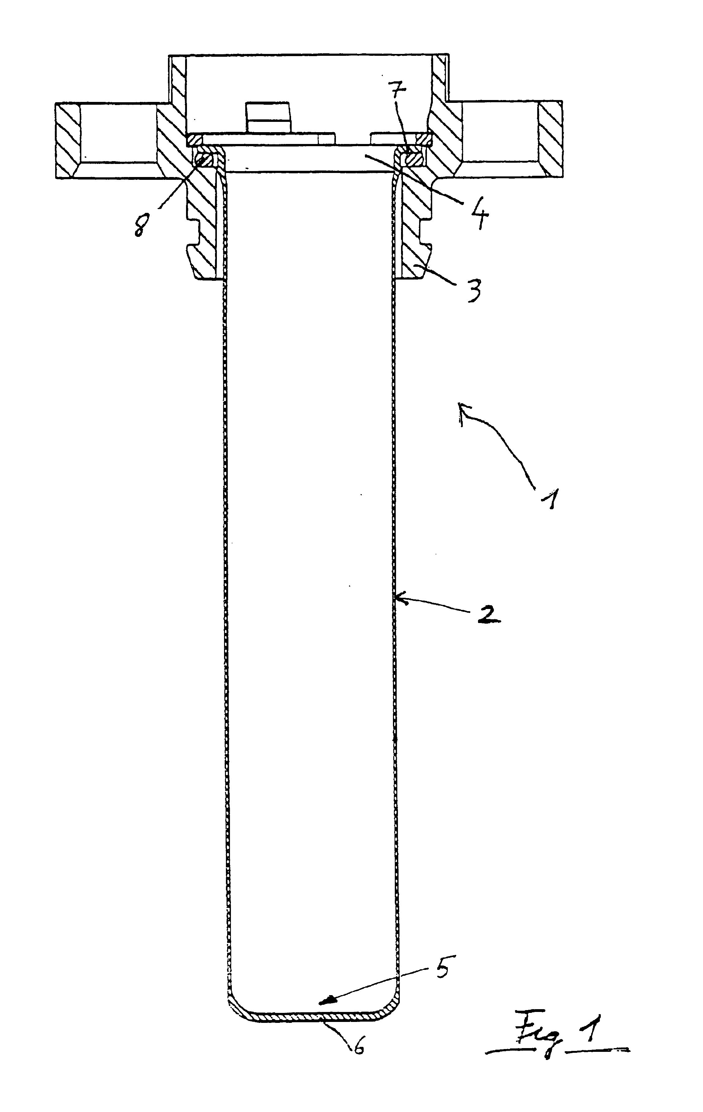
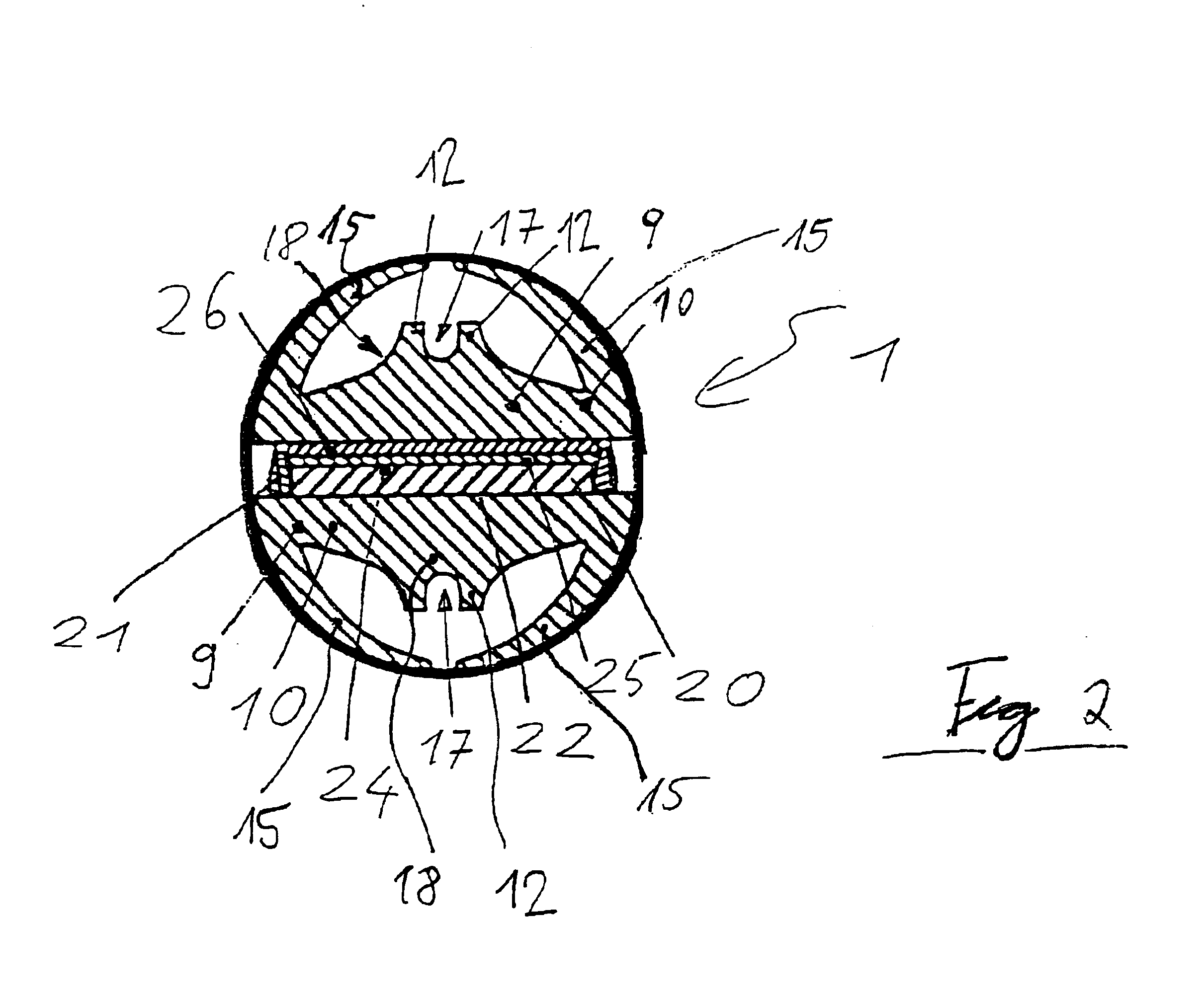
The following is a more detailed description of the structure of the heating arrangement 1:
One or more flat PTC heating elements 20 have been inserted into a frame 21, made from plastic, and have been secured in such frame against displacement. The bottom contact surfaces 22 of the PTC heating elements 20 are in direct contact with the flat side of the base 10 of a first heat dissipator 9. The upper contact surfaces 24 are completely covered by a contact plate 25. Formed integrally on the contact plate 25 is a connection element (not shown) serving as current supply, which is run to the outside from the heating arrangement 1. The contact plate 25 in turn is covered by an insulating layer 26, preferably made from a ceramic material. The insulating layer 26 is selected to be as thin as possible. The flat side of the base element 10 of a second heat dissipator 9 is placed on that insulating layer 26.
The two heat dissipators 9 preferably exhibit the same design. While current is supplie...
PUM
 Abstract
Description
Claims
Application Information