Ion trap mass spectrometer

a mass spectrometer and ion trap technology, applied in mass spectrometers, instruments, separation processes, etc., can solve the problems of less precursor ions, less fragment ions, and less amount of precursor ions, so as to improve analysis efficiency and reduce noise coming into a mass spectrum.

Inactive Publication Date: 2005-01-25
SHIMADZU CORP
View PDF7 Cites 16 Cited by
  • Summary
  • Abstract
  • Description
  • Claims
  • Application Information

AI Technical Summary

Benefits of technology

Thus, according to the present invention, a plurality of ions having distinct and separate mass to charge ratios can be selectedly left in the ion trap space while other unnecessary ions are ejected from it. In the ions ejected out of the ion trap are included such ions whose mass to charge ratios fall between the frequencies (or frequency channels) of two kinds of ions that are left in the ion trap space. There is no need to select object ions separately at different timings, so that the analyzing efficiency is much improved. The amount of selected ions is large compared to the conventional method, so that a high-sensitivity, high-precision analysis is possible. Unwanted ions falling between two object ions can be surely avoided, so that noises coming into a mass spectrum are decreased. This leads to a high-precision quantitative as well as qualitative analysis of a sample component.

Problems solved by technology

Such a method is self-evidently complicated and inefficient.
When an MS / MS analysis—in which selected ions (precursor ions) are dissociated in the ion trap space, and the mass spectrum of the dissociated fragment ions is obtained—is performed using the method, the amount of precursor ions becomes less and the amount of fragment ions also becomes less, so that an adequate mass spectrum can not be obtained.
This deteriorates the detection sensitivity, S / N ratio and precision of the mass to charge ratio of the analysis.
In the case of multivalent ions as shown in FIG. 7, ions belonging to such a group have a wide variety of mass to charge ratios, and it is actually impossible anyway to select those ions simultaneously with the above method.

Method used


Image

  • Ion trap mass spectrometer
  • Ion trap mass spectrometer
  • Ion trap mass spectrometer

Examples


Embodiment Construction

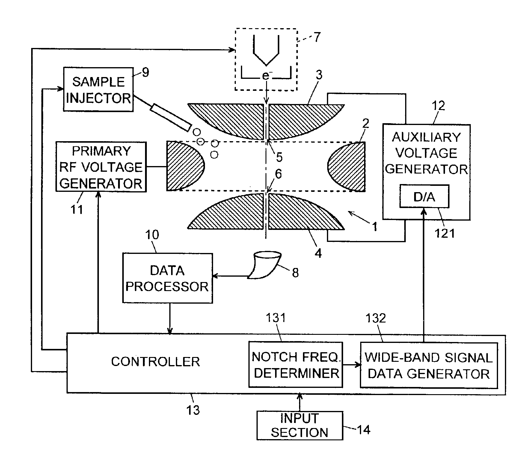
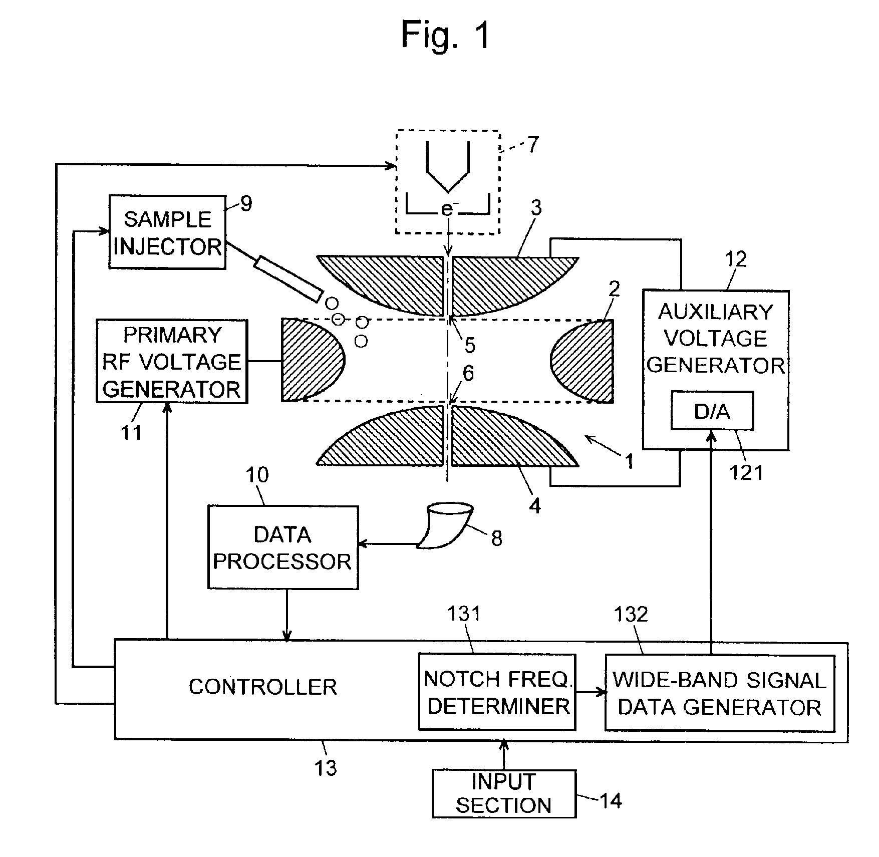
An ion trap mass spectrometer embodying the present invention is described referring to the attached drawings. FIG. 1 is a schematic diagram of the ion trap portion and its electrical system of the ion trap mass spectrometer.

The ion trap 1 is substantially composed of a ring electrode 2 and a pair of end cap electrodes 3 and 4 placed opposed to each other with the ring electrode 2 therebetween. The ring electrode 2 has a hyperboloid-of-one-sheet-of-revolution inner surface, and the end cap electrodes 3 and 4 form hyperboloid-of-two-sheets-of-revolution inner surfaces. A primary RF voltage generator 11 is connected to the ring electrode 2, and an auxiliary voltage generator 12 is connected to the first and second end cap electrodes 3 and 4. The first end cap electrode 3 has an entrance hole 5 at its center, and a thermal electron generator 7 is placed just outside the entrance hole 5. Electrons ejected from the thermal electron generator 7 are introduced through the entrance hole 5 i...


PUM

PropertyMeasurementUnit
mass to charge ratiosaaaaaaaaaa
ion trap mass spectrometeraaaaaaaaaa

Abstract

In an ion trap mass spectrometer including a ring electrode and a pair of end cap electrodes placed opposite each other with the ring electrode therebetween, where an ion trap space is defined by the ring electrode and the pair of end cap electrodes, the frequency determining section of the controller determines a plurality of frequencies or a plurality of frequency channels each corresponding to a mass to charge ratio of an ion to be selected. The wide-band RF signal generator generates a wide-band RF signal having a plurality of notches each corresponding to each of the plurality of frequencies or the plurality of frequency channels. Then the voltage controller applies a voltage corresponding to the wide-band RF voltage to the pair of end cap electrodes, whereby ions having mass to charge ratios corresponding to the frequencies or frequency channels remain in the ion trap space but other ions are ejected from the ion trap space.

Description

The present invention relates to an ion trap mass spectrometer, and especially to a method to select plural object ions from various ions stored in the ion trap.BACKGROUND OF THE INVENTIONAn ion trap mass spectrometer is composed of a ring electrode and a pair of end cap electrodes opposing each other with the ring electrode therebetween. The inner surface of the ring electrode is formed hyperboloid-of-one-sheet-of-revolution and the inner surface of the end cap electrodes are formed hyperboloid-of-two-sheets-of-revolution. When appropriate RF voltages are applied on the ring electrode and the end cap electrodes, a quadrupole electric field is formed in the space (“ion trap space”) surrounded by the ring electrode and the end cap electrodes, whereby ions generated in the ion trap space or ions introduced from outside into the space are trapped and stored there.After ions are trapped in the ion trap space, or while ions are stored there as explained above, various analyzing modes are...

Claims


Application Information

Patent Timeline
Patent Type & Authority Patents(United States)
IPC IPC(8): H01J49/42H01J49/34G01N27/62
CPCH01J49/428H01J49/424
Inventor UMEMURA, YOSHIKATSU
Owner SHIMADZU CORP
Why Eureka
Try Eureka