
Apparatus for switching windings of AC three-phase motor

a three-phase ac motor and winding technology, which is applied in the direction of motor/generator/converter stopper, electric generator control, dynamo-electric converter control, etc., can solve the problems of inability to permit the limitation of contact lifetime, the inability to switch in the high speed region, and the inability to reduce the effect of the winding, so as to minimize the influence of the switching on the machine and the device to be loaded, and the effect of winding

Inactive Publication Date: 2005-01-25
YASKAWA DENKI KK
View PDF16 Cites 23 Cited by
  • Summary
  • Abstract
  • Description
  • Claims
  • Application Information

AI Technical Summary

Benefits of technology

(1) A time required for switching a winding is shortened.
As a ripple effect, the winding can be switched in a considerably short time as compared with a switching method using a contact. Consequently, it is possible to minimize the influence of the switching on a machine and a device to be loads.

Problems solved by technology

Since the impedance of the motor is increased in proportion to a frequency, the current flow might be impeded in the high speed region in which the frequency is increased.
A limited contact lifetime itself is also a disadvantage which cannot be permitted.
Since the number of active semiconductor units to be required is large one, a cost might be a factor in impediment to practical use.

Method used


Image

  • Apparatus for switching windings of AC three-phase motor
  • Apparatus for switching windings of AC three-phase motor
  • Apparatus for switching windings of AC three-phase motor

Examples


Embodiment Construction

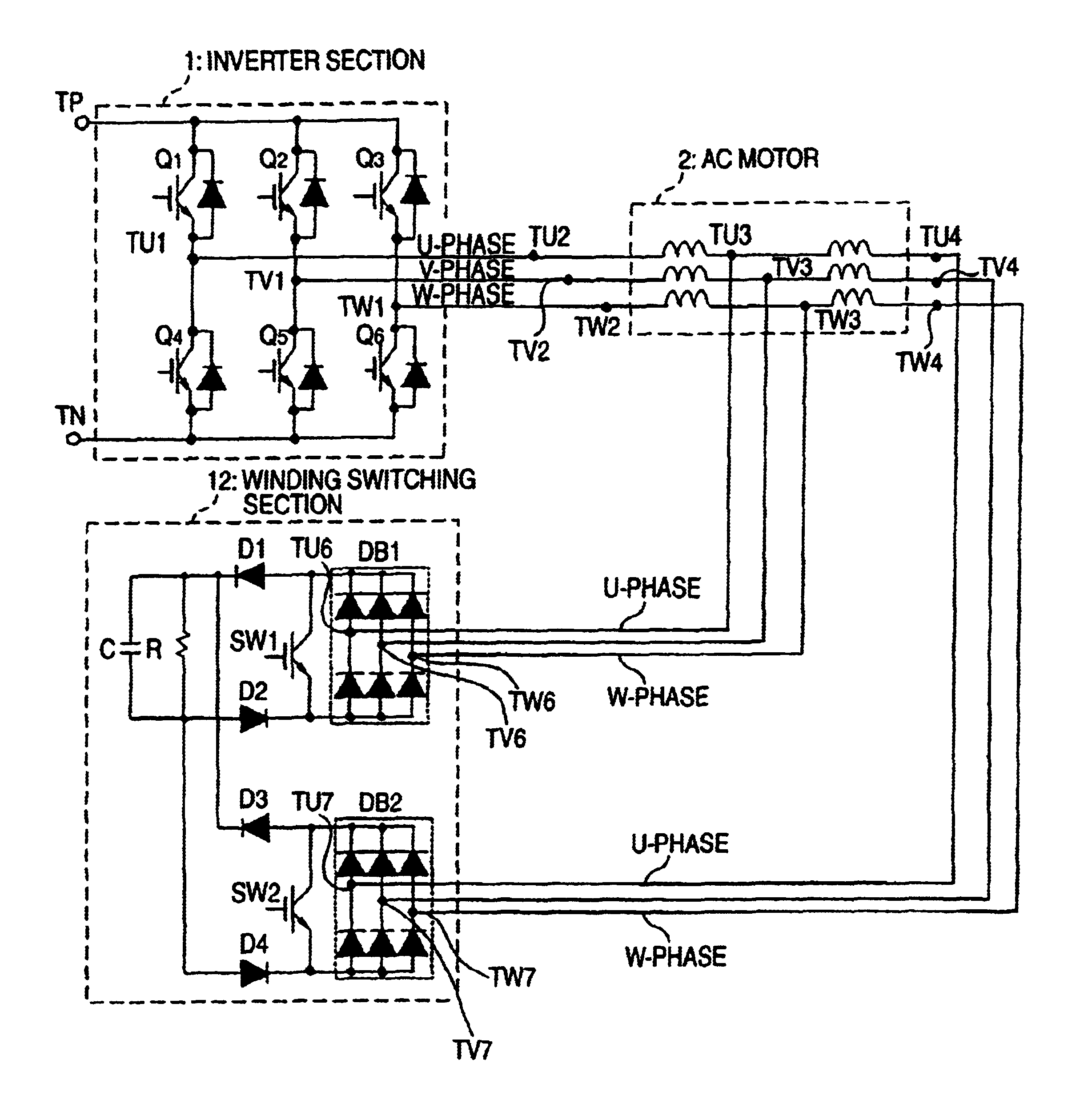
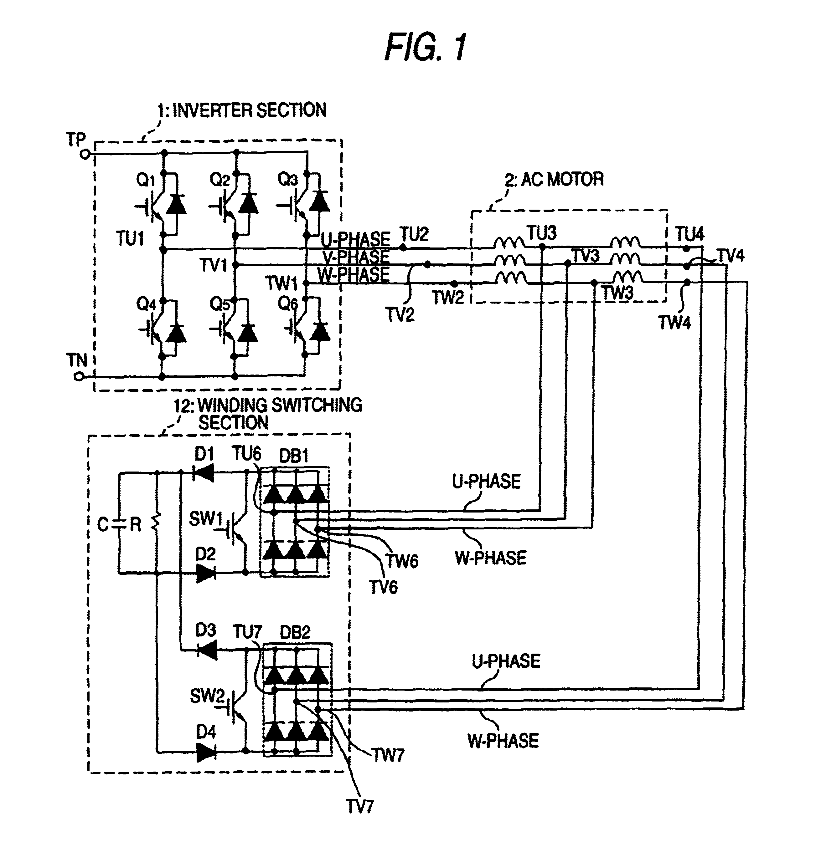
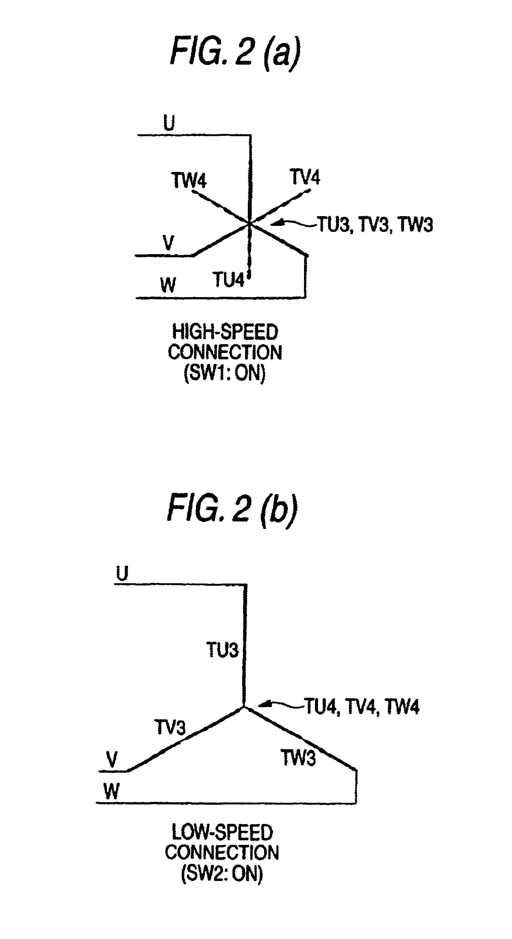
Embodiments of the invention will be described below with reference to the drawings. FIG. 1 is a diagram showing the structure of a basic circuit according to a first embodiment of the invention. In FIG. 1, 1 denotes an inverter section to be a variable frequency variable voltage source for a 3-phase motor control which is constituted by main circuit transistors Q1 to Q6. Terminals TP and TN are connected to the DC output terminal of a converter. 2 denotes an AC motor and 12 denotes a winding switching section. Each phase winding of the motor 2 is formed by two coils, and intermediate terminals TU3, TV3 and TW3 connected to the coils are taken as the external terminals of the motor. TU2, TV2 and TW2 to be the ends of winding terminals having each phase in the AC motor 2 are connected to output terminals TU1, TV1 and TW1 having each phase in the inverter section 1, respectively.

The other ends TU4, TV4 and TW4 of the winding terminals having each phase in the AC motor 2 are connected ...


PUM


Abstract

It is an object to provide a winding switching device of a three-phase AC motor having a small size at a low cost in which a time required for switching a winding is shortened and the number of semiconductor switch units is decreased as much as possible. In a winding switching device of a three-phase AC motor including an AC motor in which a winding having each phase is formed by a plurality of windings and a connecting terminal connecting the windings to each other and both terminals of the winding having the phase are provided on an outside of a motor, winding switching means for properly switching the connecting terminal, and a variable frequency power source for supplying a variable voltage having a variable frequency to the AC motor, the winding switching means is constituted by a plurality of three-phase rectifying means connecting one of ends of the winding having the phase to the variable frequency power source and connecting the other end and the connecting terminal to an input terminal on an AC side of the three-phase rectifying means for each phase, and a semiconductor switch provided to open and close both ends on a DC output side of the three-phase rectifying means.

Description

TECHNICAL FIELDThe present invention relates to a winding switching device of a three-phase AC motor for enlarging a speed control range by switching the winding of the three-phase AC motor, and is intended for a wide range of industrial field including the driving operation of a vehicle, the driving operation of the main shaft of a machine tool, the traverse motion and running of a crane, a winding machine and a servo device.BACKGROUND ARTIn the driving devices of the main shaft of a machine tool and a vehicle which are to be driven by an AC variable frequency power source, a winding switching method has been employed as means capable of obtaining a sufficiently great torque in a low speed region and carrying out an operation in a high speed region.As an example, a star-delta switching method shown in FIG. 6 has widely been used practically for the driving operation of the main shaft of a machine tool. In FIG. 6, 22 denotes a power source, 16 to 21 denote a diode constituting a thr...

Claims


Application Information

Patent Timeline
IPC IPC(8): H02P23/06H02P27/06H02P23/07H02P25/022
CPCH02P25/188H02P23/06H02P27/06
Inventor KUME, TSUNEOMAHESH, SWAMY
Owner YASKAWA DENKI KK
Learn More