Integrated circuit with a sensor element for providing an encoded output signal

a sensor element and integrated circuit technology, applied in the field of integrated circuits, can solve the problems of high emc risk of total circuits, high cost and unreliability, and complex circuit structures that are relatively bulky, and achieve simple and reliable sensor circuits, expand the field of application of sensor circuits, and increase the functionality

Inactive Publication Date: 2005-01-25
MICRONAS
View PDF13 Cites 7 Cited by
  • Summary
  • Abstract
  • Description
  • Claims
  • Application Information

AI Technical Summary

Benefits of technology

According to a preferred design, the thresholds may be adjustable. As a result, the circuit can be adapted to the particular external circumstances for forming the output signal as a function of the electrical input signal, without creating a new, corresponding sensor circuit. It is thus possible to adapt the circuit arrangement to possible time changes, such as aging effects, especially in the transducer associated with the circuit arrangement. Production tolerances or changes due to various use conditions, for example due to temperature effects and the like, can thus be taken into account simply and economically. This considerably expands the field of application of the sensor circuit, by further increasing its functionality, without requiring complex or expensive external circuits to adapt the output signal or the input signal. This results in a simple and reliable sensor circuit, which is especially characterized by an economical and flexible design.
An especially preferred design of the sensor circuit makes it possible for the user to set the thresholds himself. This can be done in a special learning mode of the s

Problems solved by technology

However, this results in a complex circuit structure that is relatively bulky, expensive and unreliable.
Fu

Method used


Image

  • Integrated circuit with a sensor element for providing an encoded output signal
  • Integrated circuit with a sensor element for providing an encoded output signal
  • Integrated circuit with a sensor element for providing an encoded output signal

Examples


Embodiment Construction

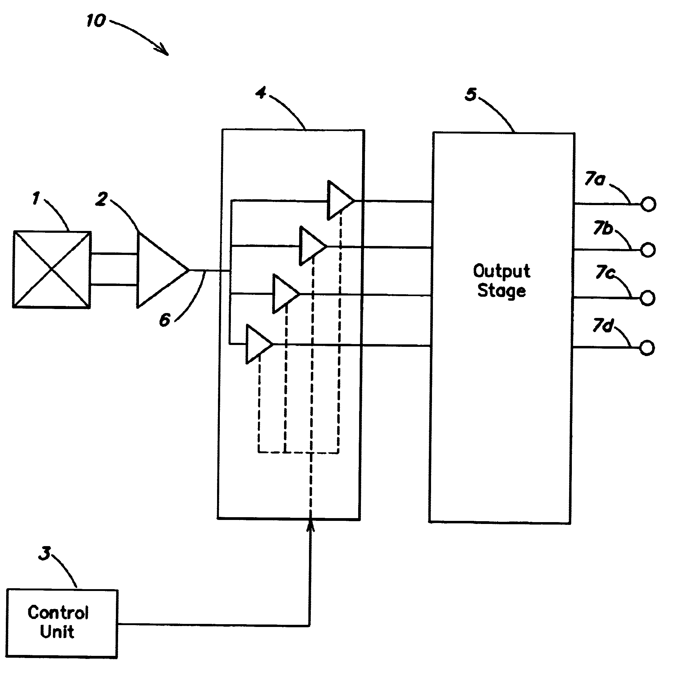
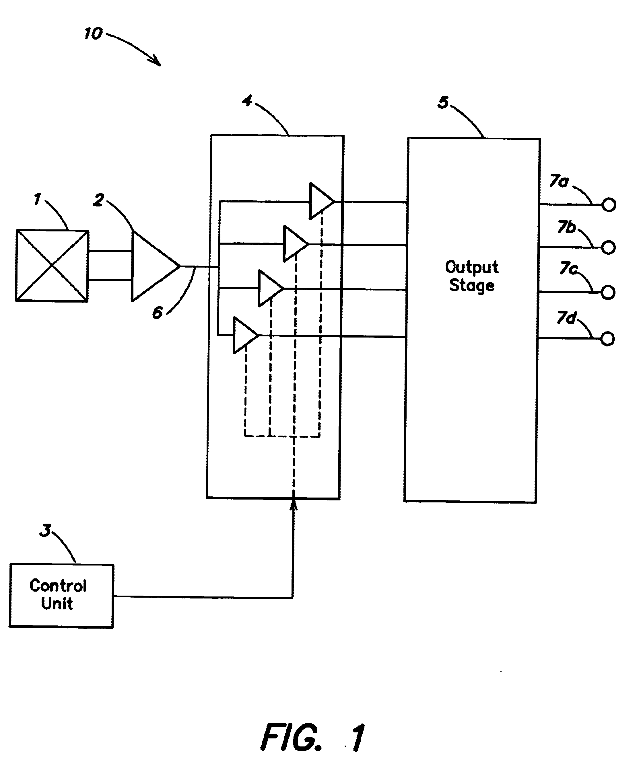
FIG. 1 is a block diagram illustration of an integrated circuit sensor 10. The sensor 10 includes a transducer 1, which converts an analog physical variable, for example a temperature or a magnetic field strength or a pressure, into an electrical signal, and conducts this signal to an amplifier 2. The amplifier 2 provides an amplified electrical signal on a line 6 to an analytical unit 4. The analytical unit 4 has a plurality of comparators, each of whose respective comparator thresholds can be adjusted by a control unit 3. The parameters for the. thresholds of the comparators in the analytical unit 4 are stored in a memory (not shown) in the control unit 3, and are used to control the comparator thresholds.

Depending on the relationship of the amplified signal on the line 6 to the respective comparator thresholds, the analytical unit 4 generates an appropriate output signal from each of the comparators, and the comparator output signals are provided to an output stage 5. The output ...


PUM


Abstract

The invention relates to an integrated circuit with a single sensor element (1) for converting a physical variable into an electrical signal, comprising a comparator unit (4) by which means the electrical signal of the sensor element (1) can be compared with various different threshold values in order to produce different discreet circuit states and an output unit (5) for outputting an output signal representing the different discreet circuit states or the comparator unit (4). The threshold values of the comparators of the comparator unit (4) are stored in a storage unit of the integrated circuit in such a way that they can be regulated with a control device (3). The integrated circuit has a single output terminal (7a) on which the various circuit states of the electrical signal can be picked off in code.

Description

BACKGROUND OF THE INVENTIONThe invention relates to an integrated circuit arrangement with a sensor element, and in particular to an integrated circuit sensor such as a magnetic field transducer that provides an encoded output signal on an integrated circuit lead.Integrated circuit arrangements with sensor elements (e.g. with magnetic sensors) that detect mechanical switching states in a large number of consumer and automotive applications are known. They detect a mechanical switching state by a variable magnetic field, which represents the changed position on the basis of a variable distance between the magnetic field sensor and a movable magnet. The physical variable of magnetic field strength is thus used as a measure for determining the switching state. If the magnet approaches the transducer, which converts the magnetic field strength into an analog electrical signal, the switching state “turned on” is represented at the output of the sensor circuit when the distance becomes le...

Claims


Application Information

Patent Timeline
IPC IPC(8): H03K17/94H03K17/945
CPCH03K17/945H03K17/94
Inventor BLOSSFELD, LOTHARJANKE, RALF
Owner MICRONAS
Why Eureka
Try Eureka