Laser distance measuring apparatus

Inactive Publication Date: 2005-01-25
MATSUSHITA ELECTRIC WORKS LTD
View PDF11 Cites 34 Cited by
  • Summary
  • Abstract
  • Description
  • Claims
  • Application Information

AI Technical Summary

Benefits of technology

The invention is devised to solve the problems of the prior art, and it is hence an object thereof to present a laser distance measuring apparatus capable of measuring the distance of two arbitrary points by one measuring apparatus, without

Problems solved by technology

That is, in order to measure the distance between two objects apart from each other, since one irradiating and measuring point of the apparatus is needed, the distance must be measured plural times by changing the apparatus installation state, using one end face of the two objects as the re

Method used


Image

  • Laser distance measuring apparatus
  • Laser distance measuring apparatus
  • Laser distance measuring apparatus

Examples


Embodiment Construction

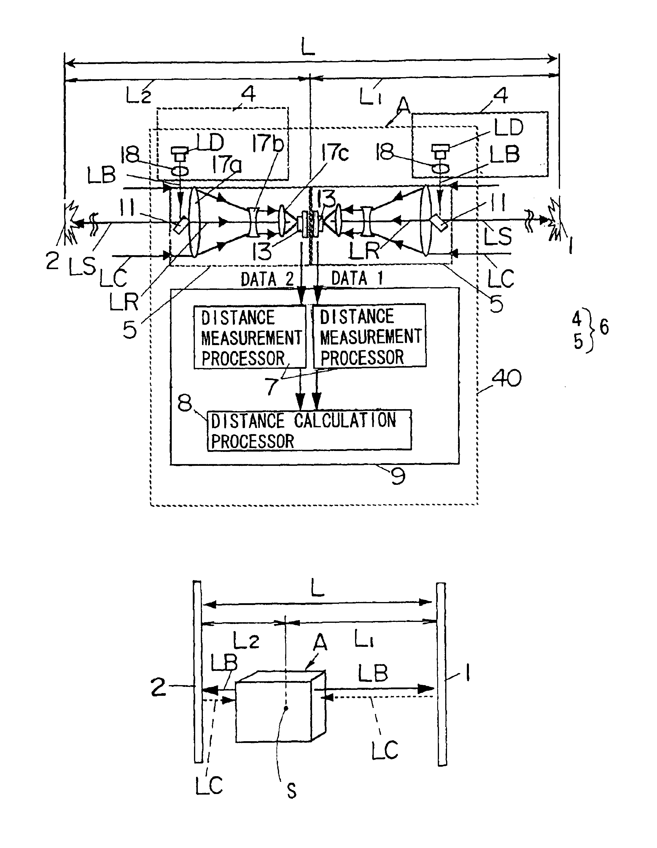
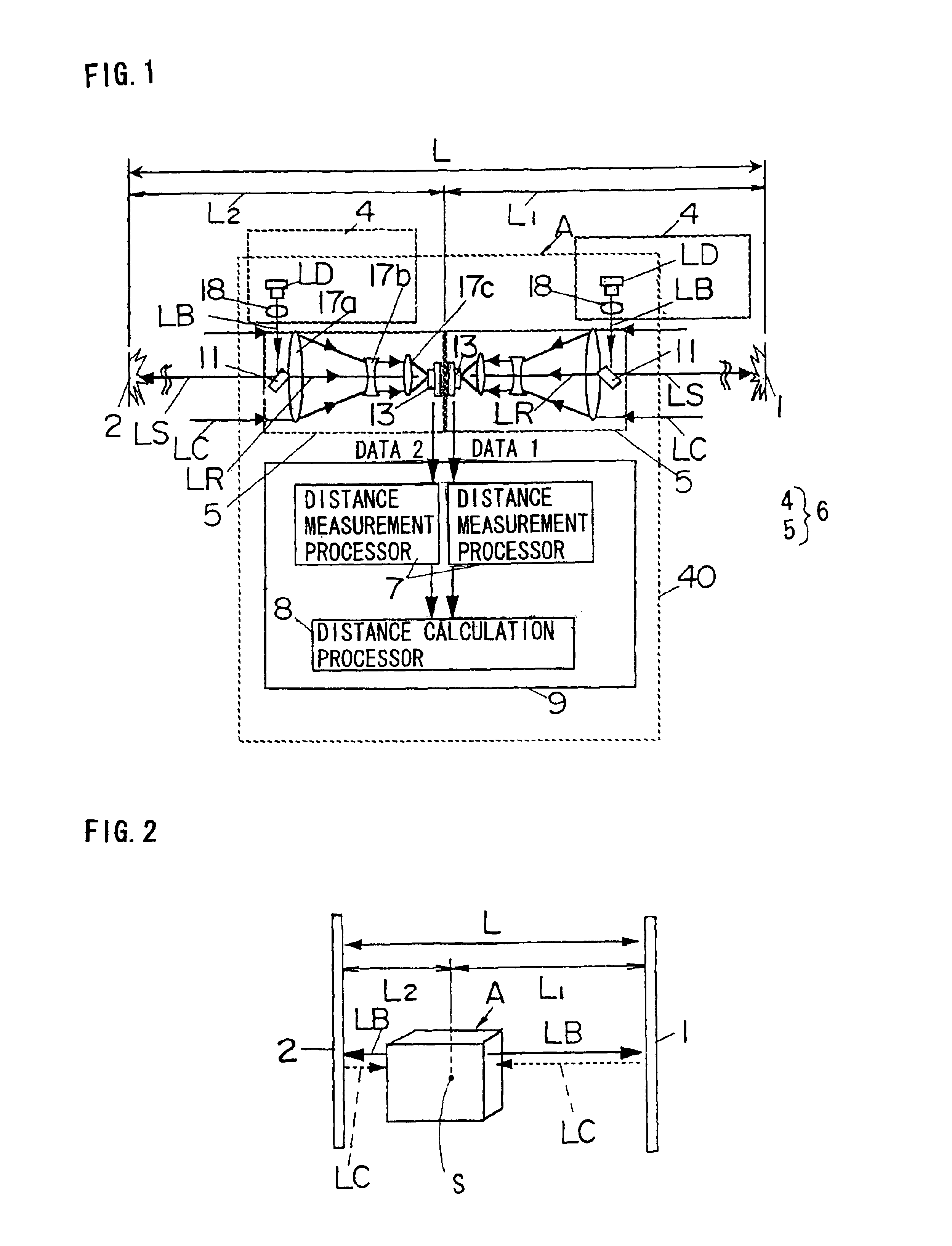
Preferred embodiments of the invention are described below while referring to the accompanying drawings. FIG. 1 shows a schematic structure in 180-degree opened state of two independent detectors in laser distance measuring apparatus A, and FIG. 2 shows its distance measuring operation. This apparatus A is composed of one casing 40, and has a pair of detectors 6 each including a projector 4 for projecting light beam LB toward objects 1, 2 positioned in plural directions as seen from the apparatus, and a photo detector 5 for receiving the reflected light LC from the objects 1, 2. The apparatus A further comprises an arithmetic processor 9 each including a distance measurement processor 7 for receiving detection signals from the photo detectors 5 and measuring distances L1, L1 from the reference point S of the apparatus to the objects 1, 2, and a distance calculation processor 8 for calculating the distance L between the objects 1, 2 (=L1+L2) on the basis of the measured distance data...


PUM


Abstract

A laser distance measuring apparatus, for measuring the distance between objects existing in two directions at least as seen from the apparatus by using laser light, comprises two projectors for projecting laser beams along a specified projection axis toward each one of the objects, a photo detector for receiving reflected light of projection from each object, a distance measurement processor for measuring the distance from a reference point of the apparatus to each object on the basis of the reception signal to the projection by the photo detector, and a distance calculation processor for calculating the distance between the objects on the basis of the distance data measured by the distance measurement processor and the angle formed by two projection axes, in which the projection axis by one projector is variable in angle with respect to the other projector. Therefore, the distance between objects can be measured easily and at high precision by one distance measuring operation only.

Description

BACKGROUND OF THE INVENTION1. Field of the InventionThe present invention relates to a laser distance measuring apparatus for calculating the distance between wall surfaces used, for example, in housing construction site or electric work site.2. Description of the Prior ArtAs distance measuring apparatus of this kind, hitherto, a dimension measuring apparatus 20 as shown in FIG. 23A is known (for example, see Japanese Laid-Open Patent Publication No. HEI 8-35820). This dimension measuring apparatus 20 comprises a cursor 22 sliding along a bar member 21, an encoder for generating a pulse at every specific moving distance of the cursor 22, photo detectors 23a, 23b for detecting the laser beam, an LCD device 24, and others. The method to use this apparatus 20 is shown in FIG. 23B, in which a laser projector 26 is installed at a reference position in a room 25, light beams are emitted in four orthogonal directions B1, B2, B3, B4, this apparatus 20 is placed in the room 25 in solid line ...

Claims


Application Information

Patent Timeline
IPC IPC(8): G01C3/08G01S17/06G01S17/00G01S17/87G01S7/481G01C15/00G01B11/03G01C3/06G01S7/48G01S17/46
CPCG01C3/08G01S17/87G01S17/06G01S7/4813G01S17/08G01S17/48G01S7/4808
Inventor HONDA, TATSUYAMAEDA, HIROSHIKISHIDA, TAKASHIYOSHIMURA, KAZUNARIOOGI, KAZUFUMIHAMAGUCHI, HIDESHINAKAMURA, YOSHIMITSUNAKAMURA, KUNINORI
Owner MATSUSHITA ELECTRIC WORKS LTD
Why Eureka
Try Eureka