Passive zero shear interferometers

a zero-shear, interferometer technology, applied in the field of interferometers, can solve the problems of reducing the accuracy of measured phase changes, reducing the accuracy of phase changes, and cyclic errors with higher harmonics, so as to reduce beam shear and reduce beam shear.

Inactive Publication Date: 2005-01-25
ZYGO CORPORATION
View PDF33 Cites 82 Cited by
  • Summary
  • Abstract
  • Description
  • Claims
  • Application Information

AI Technical Summary

Benefits of technology

Beam shear (e.g., relative beam shear) can be reduced (e.g., eliminated) in an interferometric system by conditioning an input beam prior to directing the input beam to the interferometer. Accordingly, the invention features apparatus and methods for reducing beam shear in an interferometer and/or for reducing beam shear in an output beam of an interferometer. Conditioning the input beam reduces beam shear associated with changes in the position (e.g., orie

Problems solved by technology

Components of the exit measurement and reference beams in the mixed beam interfere with one another so that the intensity of the mixed beam varies with the relative phase of the exit measurement and reference beams.
Unfortunately, this equality is not always exact.
A variable amplitude may subsequently reduce the accuracy of measured phase changes.
Higher harmonic cyclic errors can also be present.
Inhomogeneities in the interferometer optics may cause wavefr

Method used


Image

  • Passive zero shear interferometers
  • Passive zero shear interferometers
  • Passive zero shear interferometers

Examples


first embodiment

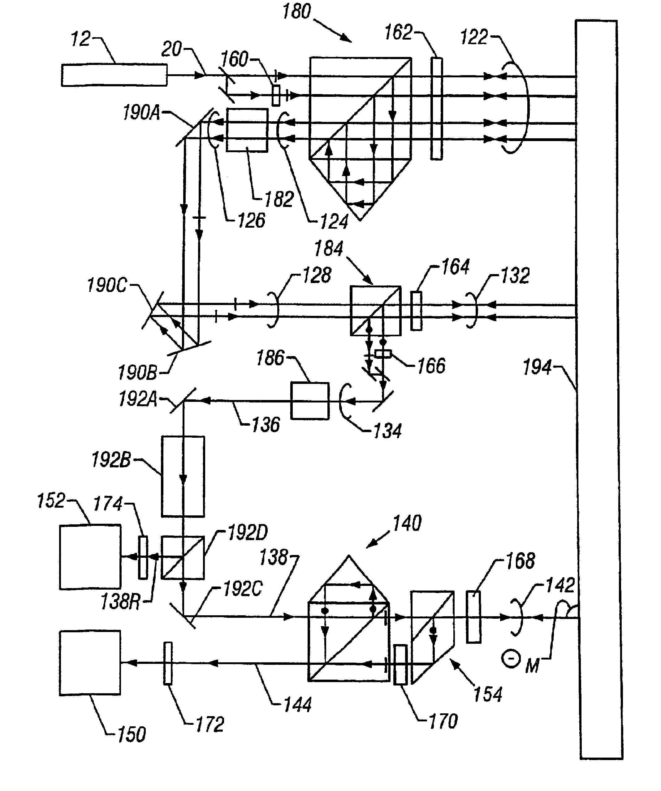
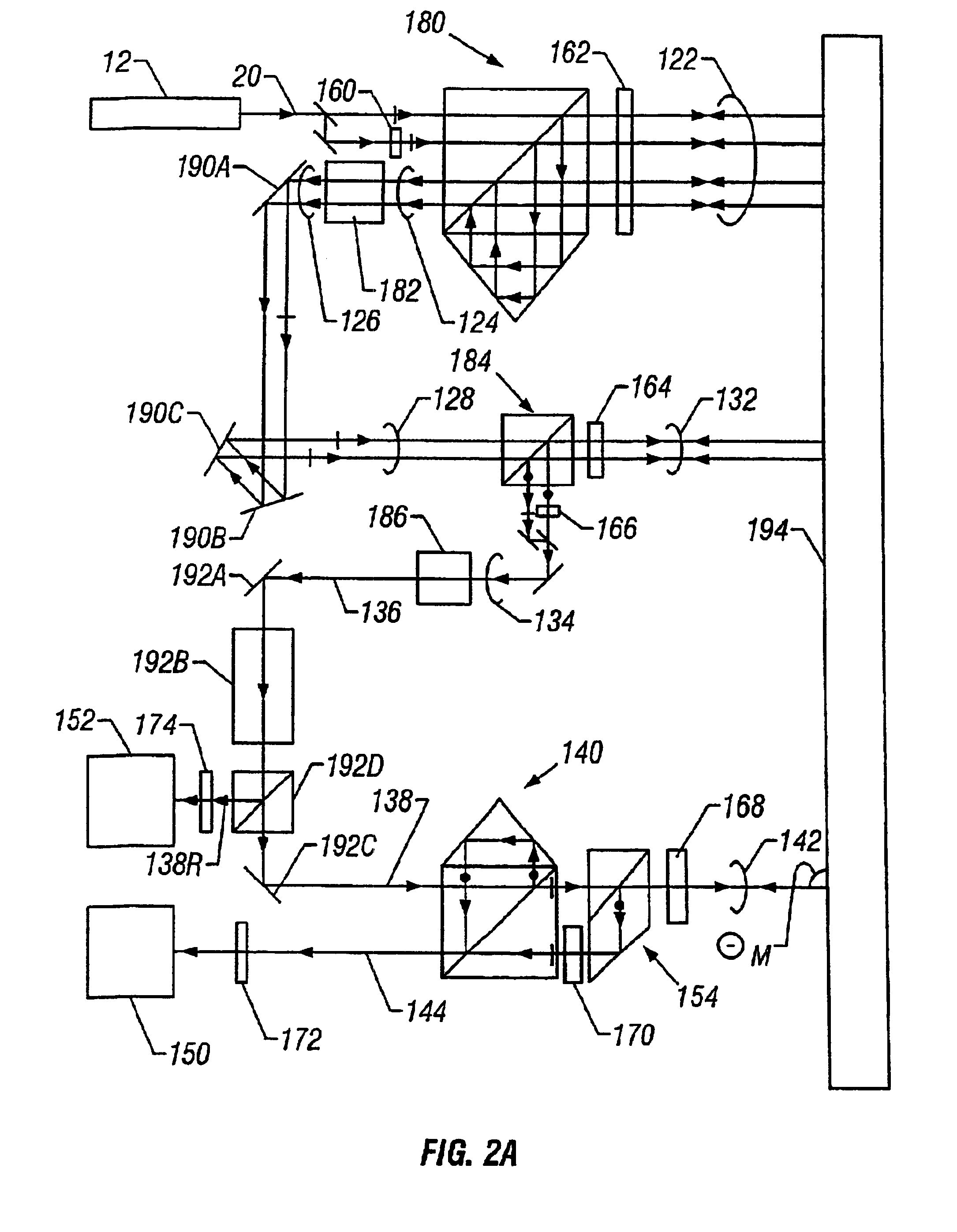
the present invention is shown diagrammatically in FIG. 2a. The beam conditioner of the first embodiment comprises a differential plane mirror interferometer shown generally at 180 wherein plane mirror 194 serves as both the reference and measuring objects. The beam conditioner further comprises a single pass plane mirror interferometer generally shown at 184 wherein the reference and measurement objects are also plane mirror 194. The remaining components of the beam conditioner are afocal systems 182 and 186 and beam relay system comprising elements 190A, 190B, and 190C.

The description of source 12 and input beam 20 of the first embodiment is the same as the description given for the corresponding elements shown in FIG. 1. Input beam 20 is incident on interferometer 180 to form beam 122 and output beam 124. Beam 122 comprises both reference and measurement beams that each makes a double pass to mirror 194. Elements 160 and 162 are half wave and quarter wave phase retardation plates...

second embodiment

A second embodiment is shown diagrammatically in FIG. 3. The second embodiment comprises many elements with functions the same as like numbered elements of the first embodiment. the present invention measures displacements of mirror 194 at two different spots on the reflecting surface of mirror 194 by two single pass interferometers wherein the measurement beams of the two single beam interferometers are orthogonal to the reflecting surface of mirror 194 independent of changes of orientation of mirror 194. In addition, there are substantially no shears of reference and measurement beams in the two single beam interferometers and the shear of measurement beams of the two single beam interferometers at mirror 194 is the same as the shear of the corresponding measurement beam at mirror 194 of the first embodiment. Displacements measured by the two single beam interferometers are used to monitor linear displacements of mirror 194 and the change in orientation of mirror 194 in one plane....

third embodiment

A third embodiment is shown diagrammatically in FIG. 4a. The third embodiment comprises many elements with functions the same as like numbered elements of the first embodiment. the present invention measures displacements of mirror 194 at one spot on the reflecting surface of mirror 194 by a double pass interferometer 240 wherein the measurement beams of the double pass interferometer 240 are orthogonal to the reflecting surface of mirror 194 independent of changes of orientation of mirror 194. In addition, there are substantially no shears of reference and measurement beams in double pass interferometer 240 and the shear of measurement beams of the double pass interferometer 240 at mirror 194 is the same as the shear of the corresponding measurement beam at mirror 194 of the first embodiment. Displacements measured by the double pass interferometer are used to monitor linear displacements of mirror 194.

Output beam 244 of interferometer 240 is transmitted by polarizer 272 to form a ...


PUM


Abstract

Beam shear can be reduced in an interferometric system by conditioning an input beam prior to directing the input beam to an interferometer. Accordingly, apparatus and methods for conditioning an interferometer input beam are disclosed.

Description

BACKGROUNDThis invention relates to interferometers, e.g., displacement measuring and dispersion interferometers that measure angular and linear displacements of a measurement object such as a mask stage or a wafer stage in a lithography scanner or stepper system.Displacement measuring interferometers monitor changes in the position of a measurement object relative to a reference object based on an optical interference signal. The interferometer generates the optical interference signal by overlapping and interfering a measurement beam reflected from the measurement object with a reference beam reflected from the reference object.In many applications, the measurement and reference beams have orthogonal polarizations and different frequencies. The different frequencies can be produced, for example, by laser Zeeman splitting, by acousto-optical modulation, or internal to the laser using birefringent elements or the like. The orthogonal polarizations allow a polarizing beam splitter to...

Claims


Application Information

Patent Timeline
IPC IPC(8): G01B9/02
CPCG03F7/70775G01B9/02019G01B9/02061G01B9/02018G01B9/02003G01B2290/70
Inventor HILL, HENRY A.
Owner ZYGO CORPORATION
Why Eureka
Try Eureka