Magnetic tunnel junction device with bottom free layer and improved underlayer

a tunnel junction and free layer technology, applied in the field of magnetic tunnel junction devices, can solve the problems of corroding of antiferromagnetic materials and aluminum oxide typically used for tunnel barriers during abs lapping process, poor interface to tunnel barriers or flux guides which are too thin to be useful, and difficulty in forming tunnel barrier layers thin enough

Inactive Publication Date: 2005-01-25
WESTERN DIGITAL TECH INC
View PDF3 Cites 67 Cited by
  • Summary
  • Abstract
  • Description
  • Claims
  • Application Information

AI Technical Summary

Benefits of technology

The invention is a magnetic tunnel junction device with the free ferromagnetic layer located on the bottom of the device, the bottom free layer being formed on a special underlayer. The underlayer is an alloy comprising Mn, one of Pt, Ni, Ir and Os, and an additive X selected from Ta, Al, Ti, Cu, Cr and V. Without the additive, the alloy is antiferromagnetic. The additive is present in an amount sufficient to render the alloy to have no magnetic ordering, i.e., it is neither antiferromagnetic nor ferromagnetic, but without substantially affecting the preferred crystalline texture and unit cell size so that the underlayer is well-suited as a growth-enhancing underlayer for the free ferromagnetic layer. In one embodiment the device is an MTJ read head that has the special underlayer formed over the head's bottom magnetic shield and the free ferromagnetic layer deposited on the underlayer, with the underlayer being PtMnTa or PtMnAl, with Cr or Al present between about 5 and 20 atomic percent. The underlayer may be deposited on the bottom shield or on an adhesion layer, such as Ta, Cr, Ti, NiFe, Ru, or Cu, with the adhesion layer being deposited on the bottom shield. The PtMnCr or PtMnAl underlayer thickness is not critical to the smoothness of the tunnel barrier layer that is subsequently deposited on the free ferromagnetic layer. This allows the tunnel barrier to be made sufficiently thin to achieve the desired electrical resistance, and is also a significant advantage in an MTJ read head because by making the underlayer thicker the free ferromagnetic layer can be located substantially at the center of the gap between the top and bottom magnetic shields.

Problems solved by technology

In addition, many antiferromagnetic materials and the aluminum oxide typically used for the tunnel barrier can also corrode during the ABS lapping process.
A flux-guided MTJ read head as shown in FIG. 1, wherein the free ferromagnetic layer is on top, is not the most desirable type of structure because it requires deposition of the free layer following formation of the recessed layers in the MTJ, which causes a poor interface to the tunnel barrier or a flux guide which is too thin to be useful.
The problem with forming the free ferromagnetic layer on the bottom is that the tunnel barrier layer becomes rough when the bottom free layer is grown on the conventional underlayer, typically Ta, which makes it difficult to form the tunnel barrier layer thin enough.
However, it is known that increasing the Ta underlayer thickness to achieve this free layer positioning does not improve the smoothness of the tunnel barrier layer.

Method used


Image

  • Magnetic tunnel junction device with bottom free layer and improved underlayer
  • Magnetic tunnel junction device with bottom free layer and improved underlayer
  • Magnetic tunnel junction device with bottom free layer and improved underlayer

Examples


Embodiment Construction

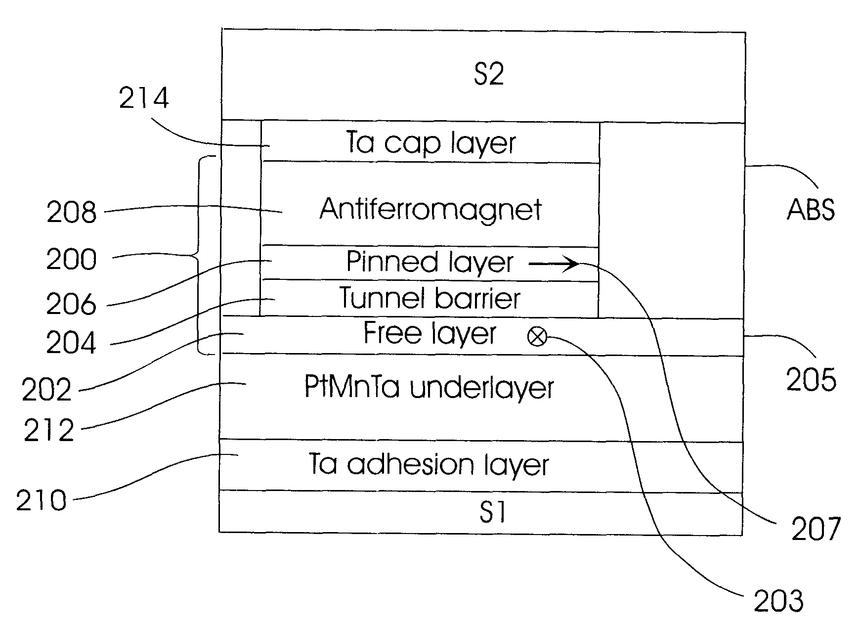
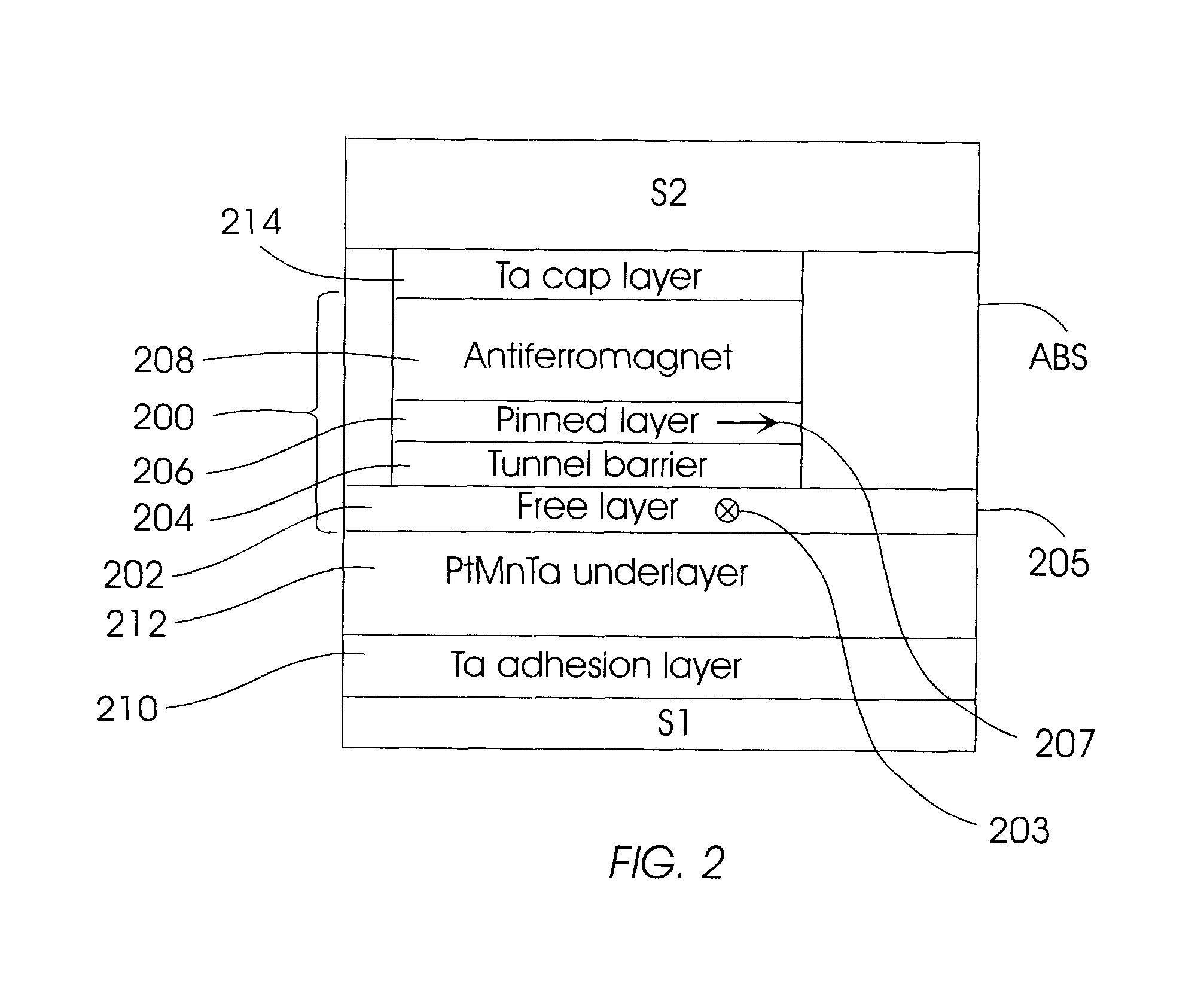
The MTJ device according to the present invention with the free layer on the bottom is fully applicable as a magnetic memory cell or as an MTJ read head without the use of the free layer as a flux guide, but is shown in FIG. 2 as a flux-guided MTJ read head. In FIG. 2, the MTJ 200 is an “inverted” structure with the free ferromagnetic layer 202 being the bottom ferromagnetic layer and formed on an improved underlayer 212. The underlayer 212 is a non-magnetically ordered Mn alloy, preferably PtMnTa, and is formed on a Ta adhesion layer 210 on top of the bottom magnetic shield S1. The MTJ 200 includes the free layer 202, the tunnel barrier layer 204, the pinned ferromagnetic layer 206 and the antiferromagnetic layer 208 exchange coupled with the pinned ferromagnetic layer 206 and a Ta cap layer 214 . As shown, the free layer 202 has its front edge 205 coplanar with the ABS for sensing magnetically recorded data from the magnetic layer on the disk. The magnetic moment 207 of the pinned...


PUM

PropertyMeasurementUnit
magnetic orderaaaaaaaaaa
magnetic momentaaaaaaaaaa
magnetic fieldaaaaaaaaaa

Abstract

A magnetic tunnel junction (MTJ) device usable as a magnetic memory cell or magnetoresistive sensor, such as a MTJ read head for magnetic recording, has the free ferromagnetic layer located on the bottom of the device, the bottom free layer being formed on a special underlayer. The MTJ read head may be a flux-guided head that uses the free layer as a flux guide for directing magnetic flux from the magnetic media to the sensing region of the MTJ. The special underlayer for the growth of the free layer is an alloy comprising Mn, one of Pt, Ni, Ir and Os, and an additive X selected from Ta, Al, Ti, Cu, Cr and V. Without the additive, the underlayer alloy is antiferromagnetic. The additive is present in an amount sufficient to render the alloy to have no magnetic ordering, i.e., it is neither antiferromagnetic nor ferromagnetic, but without substantially affecting the preferred crystalline texture and unit cell size so that the underlayer is well-suited as a growth-enhancing underlayer for the free layer.

Description

TECHNICAL FIELDThis invention relates in general to magnetic tunnel junction (MTJ) devices, and more particularly to an MTJ device with the free layer being the bottom ferromagnetic layer.BACKGROUND OF THE INVENTIONMagnetic tunnel junction (MTJ) devices are comprised of two ferromagnetic layers separated by a thin insulating tunnel barrier layer and are based on the phenomenon of spin-polarized electron tunneling. The insulating tunnel barrier layer is thin enough that quantum mechanical tunneling occurs between the ferromagnetic layers. The tunneling phenomenon is electron-spin dependent, making the magnetic response of the MTJ device a function of the relative orientations and spin polarizations of the two ferromagnetic layers.MTJ devices have been proposed as memory cells for use in nonvolatile magnetic random access memory (MRAM) arrays. In an MRAM the resistance of the MTJ memory cell is lowest when the magnetic moments or magnetization directions of both ferromagnetic layers a...

Claims


Application Information

Patent Timeline
Patent Type & Authority Patents(United States)
IPC IPC(8): G11B5/39G11B5/31H01L43/08
CPCB82Y10/00B82Y25/00H01L43/08G11B5/3903G11B5/3909G11B5/313H10N50/10
Inventor CHILDRESS, JEFFREY R.FONTANA, JR., ROBERT E.HO, KUOK SANTSANG, CHING HWA
Owner WESTERN DIGITAL TECH INC
Why Eureka
Try Eureka