X-ray detector with an applied stray radiation grid, and method for applying a stray radiation grid to an X-ray detector

a radiation grid and detector technology, applied in the direction of diaphragm/collimeter handling, originals for photomechanical treatment, instruments, etc., can solve the problem of reducing the recognizability of fine contrast differences, additional noise, and noticeable loss of primary radiation at the edges of image exposure, so as to achieve high detective quantum efficiency

Inactive Publication Date: 2005-01-25
SIEMENS AG
View PDF2 Cites 10 Cited by
  • Summary
  • Abstract
  • Description
  • Claims
  • Application Information

AI Technical Summary

Benefits of technology

An object of the present invention is to provide an X-ray detector and a method for the application of a stray radiation grid onto an X-ray detect...

Problems solved by technology

Due to unavoidable interactions, however, the X-rays emanating from the X-ray source are scattered in the subject, so that scattered rays, referred to as secondary rays, are also incident onto the detector in addition to the primary rays.
These scattered rays, which can cause up to more than 90% of the overall signal modulation of an X-ray detector in diagnostic images dependent on properties of the subject, represent an additional noise source and therefore diminish the recognizability of fine contrast differences.
This serious disadvantage of the stray radiation is due to a significant, additional noise component in the image exposure caused by the quantum property of the stray radiation.
This, however, leads to a noticeable loss of primary radiation at the edges of the image exposure since a larger part of the incident primary radiation strikes the absorbent regions of the stray radiation grid at these locations.
The scattered rays should be absorbed as well as possible; however, as much of the primary radiation as possible should pass through the stray radiation grid unattenuated.
However, ima...

Method used


Image

  • X-ray detector with an applied stray radiation grid, and method for applying a stray radiation grid to an X-ray detector
  • X-ray detector with an applied stray radiation grid, and method for applying a stray radiation grid to an X-ray detector
  • X-ray detector with an applied stray radiation grid, and method for applying a stray radiation grid to an X-ray detector

Examples


Embodiment Construction

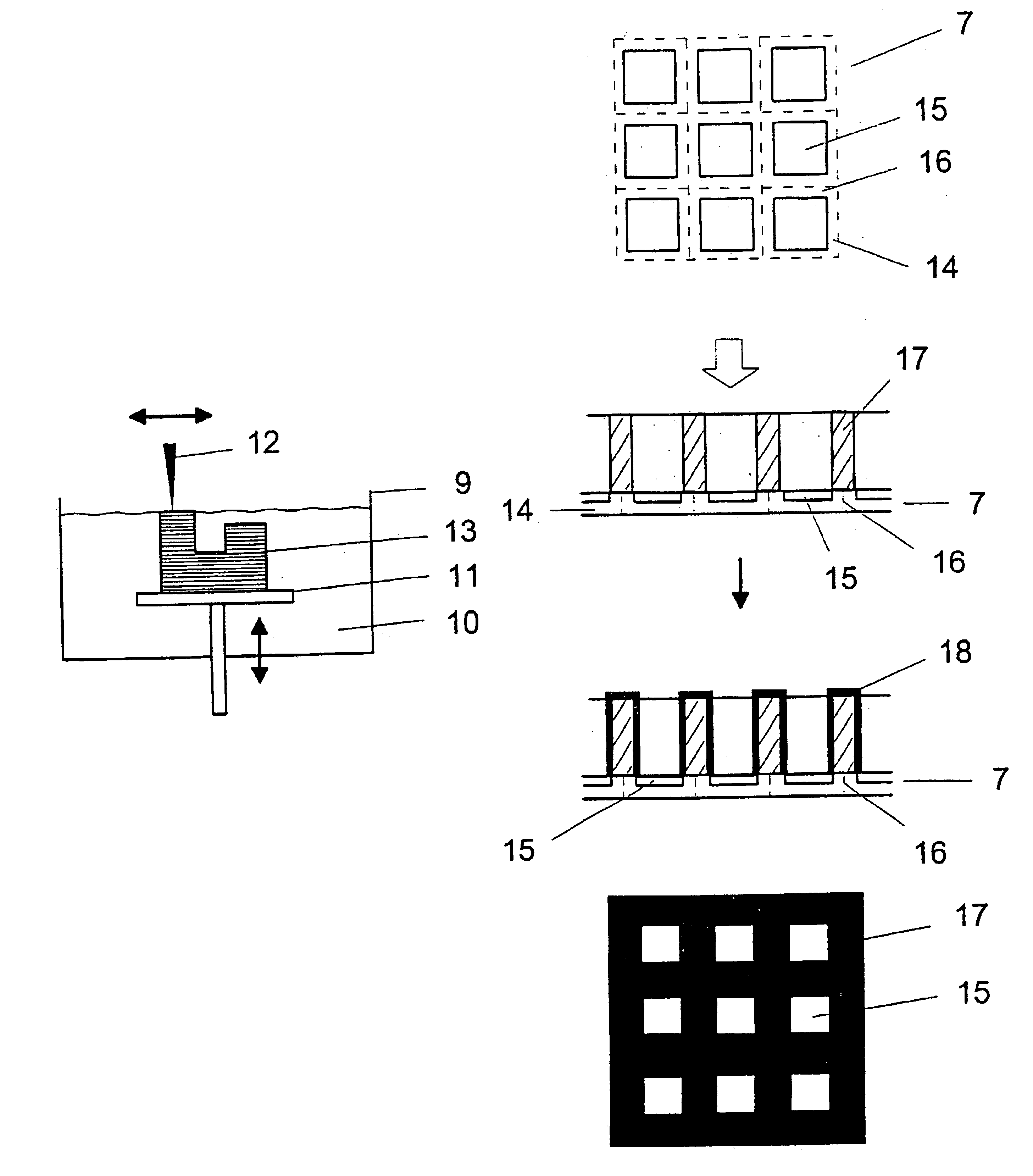
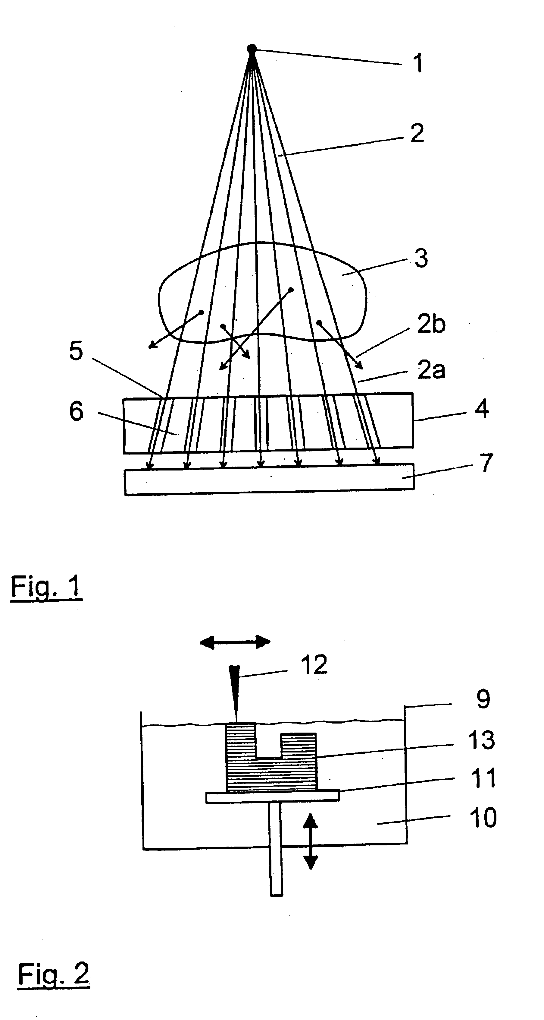
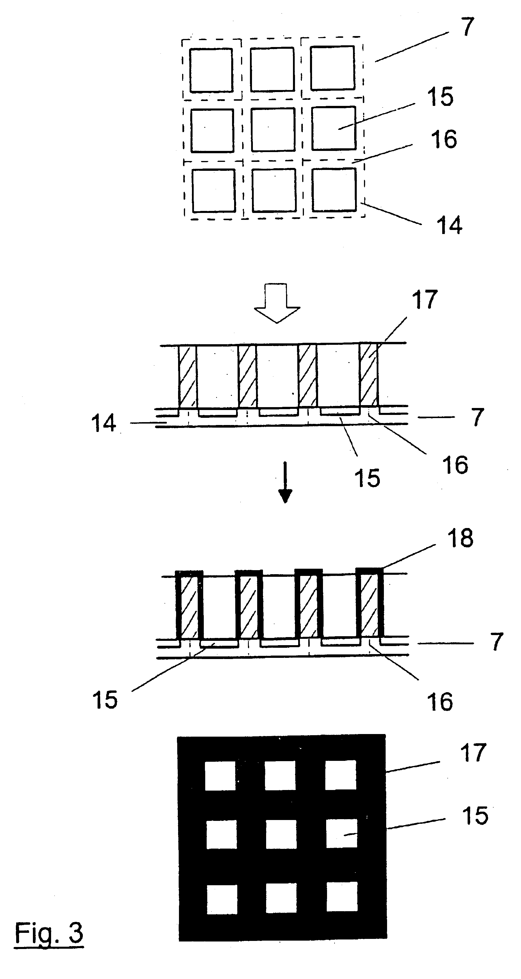
The typical relationships in an X-ray image exposure of a subject 3 in X-ray diagnostics are schematically shown on the basis of FIG. 1. The subject 3 is situated between the tube focus 1 of an X-ray tube, which can be considered as an approximately punctiform X-ray source, and a detector surface 7. The X-rays 2 emanating from the focus 1 of the X-ray source propagate on a straight line in the direction of the X-ray detector 7 and thereby penetrate the subject 3. The primary rays 2a that penetrate the subject 3 on a straight line proceeding from the focus 1 and which strike the detector surface 7 produce a topically resolved attenuation value distribution for the subject 3 on the detector surface 7. Some of the X-rays 2 emanating from the X-ray focus are scattered in the subject 3. The scattered rays 2b that thereby arise do not contribute to the desired image information and considerably degrade the signal-to-noise ration when they strike the detector 7. A stray radiation grid 4 th...


PUM


Abstract

In an X-ray detector and method for applying a stray radiation grid onto an X-ray detector having detector elements arranged in a matrix that form a detector surface having detection regions sensitive to X-rays and less sensitive intermediate regions, a basic structure for the stray radiation grid is built up over the detector surface directly on the X-ray detector with a rapid prototyping technique and is subsequently coated or filled with a material that is highly absorbent for X-radiation. An absorbent structure thus arises that lies over the less sensitive intermediate regions of the detector surface. Moiré disturbances are avoided in the X-ray image exposure and the detective quantum efficiency (DQE) is increased.

Description

BACKGROUND OF THE INVENTION1. Field of the InventionThe present invention is directed to a method for applying a stray radiation grid having detector elements arranged in a matrix, and is also directed to an X-ray detector having a stray radiation grid that applied by such a method.2. Description of the Prior ArtIn X-ray image technology, high demands are currently made of the image quality of the X-ray exposures. For making such exposures, particularly as implemented in medical X-ray diagnostics, a subject to be examined is transirradiated by X-rays of an approximately punctiform X-ray source, and the attenuation distribution of the X-rays is two-dimensionally acquired at that side of the subject opposite the X-ray source. A line-by-line acquisition of the X-rays attenuated by the subject also can be undertaken, for example in computed tomography installations. In addition to X-ray films and gas detectors, solid-state detectors are being increasingly utilized, these usually having ...

Claims


Application Information

Patent Timeline
IPC IPC(8): G21K1/02
CPCG21K1/025B33Y80/00B33Y40/20
Inventor HOHEISEL, MARTINSKLERITZ, HARTMUT
Owner SIEMENS AG
Why Eureka
Try Eureka