Optical waveguide and method for manufacturing the same

Active Publication Date: 2005-01-25
PANASONIC CORP
View PDF7 Cites 15 Cited by
  • Summary
  • Abstract
  • Description
  • Claims
  • Application Information

AI Technical Summary

Benefits of technology

It is preferable that the core material is a resin solution including the polymeric material and a solvent; the core material of the resin solution is applied to the surface of the first cladding that is provided with the groove, and the groove is filled with the core material; the core material is heated to change the refractive index, and the core material other than that filled in the groove is removed by polishing; and the second cladding is bonded to the surface of the first cladding that is provided with the groove by direct bonding after the polishing. According to this method, a low-loss high-performance optical waveguide can be produced easily. The method also can facilitate the control of the refractive index of the core.
It is preferable that an adhesive is applied to at least one of the surface of the first cladding that is provided with the groove and the surface of the second cladding that is bonded to the first cladding after the removal of the core material by polishing, and the first cladding and the second cladding are bonded together via the adhesive. The adhesive may have a refractive index substantially equal to that of the second cladding. This method can bond the first cladding and the second cladding easily without heating, prevent the degradation of performance, and achieve high productivity.
It is preferable that the core material is a resin solution including the polymeric material and a solvent; the core material of the resin solution is applied to at least one of the surface of the first cladding that is provided with the groove and the surface of the second cladding that is bonded to the first cladding; the core material is pressed between the first cladding and the second cladding, and then is heated to change the refractive index; the groove is filled with the core material; and the first cladding and the second cladding are bonded together via the core material. According to this method, the refractive index of the core material can be controlled while the first cladding and the second cladding are bonded together. Thus, it is possible to reduce the number of steps in the fabrication of an optical waveguide.
It is preferable that the core material is a resin solution including at least the polymeric material and a solvent; the core material of the resin s

Problems solved by technology

At present, resin is inferior to quartz in both transmission capacity and reliability.
However, complicated equipment is required to perform the dry etching.
Therefore, the conventional method has the problems of cost and productivity.
However, the groove-filling technique causes different problems when a quartz material is used as the core material and when a resin material, typified by acrylic resin, epoxy resin, or polyimide resin, is used as the core material.
It takes a considerable length of time to form such a thick film, which resu

Method used


Image

  • Optical waveguide and method for manufacturing the same
  • Optical waveguide and method for manufacturing the same
  • Optical waveguide and method for manufacturing the same

Examples


Example

Embodiment 1

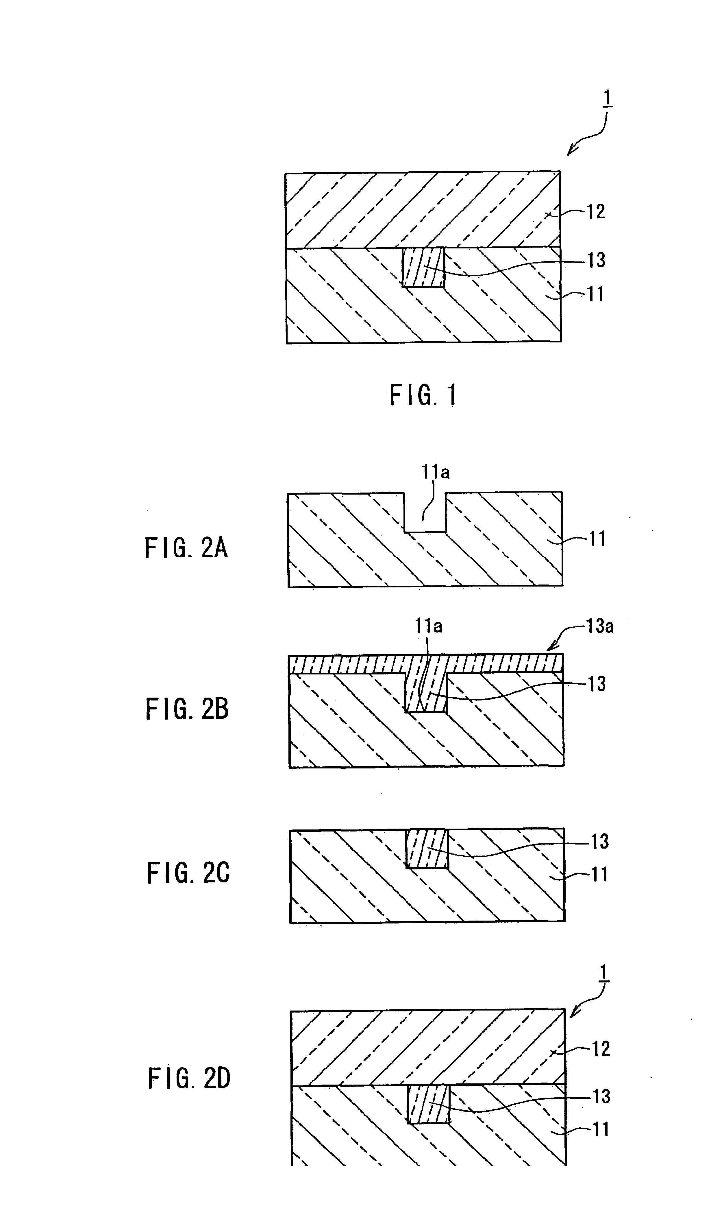
An optical waveguide of Embodiment 1 of the present invention will be described with reference to the drawings. FIG. 1 is a cross-sectional view showing the configuration of an optical waveguide 1. As shown in FIG. 1, the optical waveguide 1 includes a core 13 and glass substrates (claddings) 11, 12 that surround the core 13. A guided optical wave is trapped and propagated in the core 13.

The core 13 is embedded in the glass substrate 11 so as to be exposed on the principal surface of the glass substrate 11 that is opposed to the glass substrate 12. The glass substrates 11, 12 are arranged so as to sandwich the core 13. The glass substrates 11, 12 can be made of the same material.

A product formed, e.g., by heating a polymeric material that includes branched polysilane and polysiloxane is used as the core 13. The cross section of the core 13 is, e.g., 8 μm square. It is preferable that a relative refractive index difference between the core 13 and the glass substrates (cla...

Example

Embodiment 2

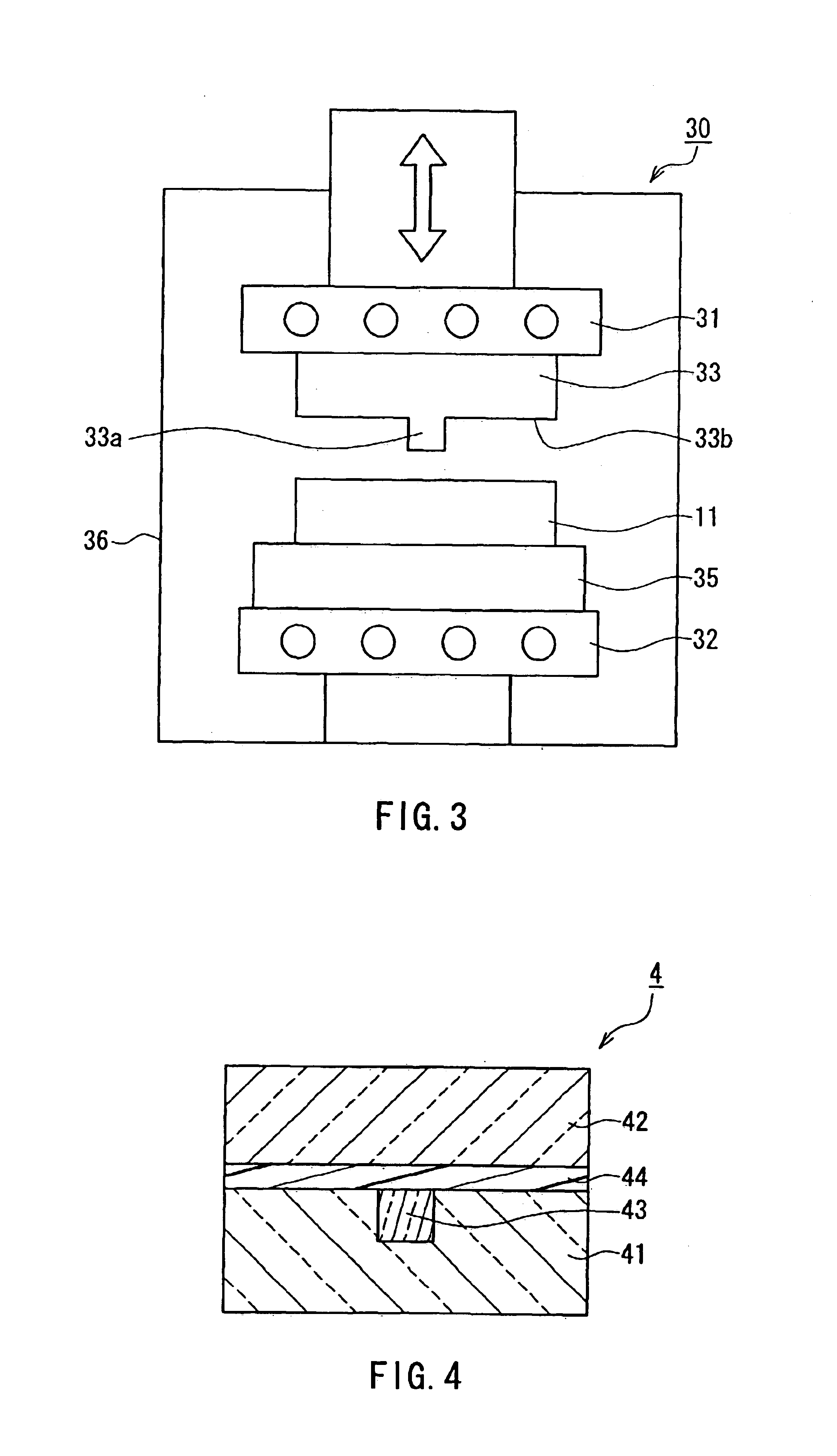
An optical waveguide of Embodiment 2 of the present invention will be described with reference to the drawings. FIG. 4 is a cross-sectional view showing the configuration of an optical waveguide 4. As shown in FIG. 4, the optical waveguide 4 includes a core 43, glass substrates (claddings) 41, 42 that surround the core 43, and an adhesive layer 44. A guided optical wave is trapped and propagated in the core 43.

The core 43 is embedded in the glass substrate 41 so as to be exposed on the principal surface of the glass substrate 41 that is opposed to the glass substrate 42. The glass substrates 41, 42 are arranged so as to sandwich the core 43 via the adhesive layer 44. The glass substrates 41, 42 can be made of the same material. The refractive index of the adhesive layer 44 can be the same as the refractive indices of the glass substrates 41, 42.

A product formed, e.g., by heating a polymeric material that includes branched polysilane and polysiloxane is used as the core 4...

Example

Embodiment 3

An optical waveguide of Embodiment 3 of the present invention will be described with reference to the drawings. FIG. 7 is a cross-sectional view showing the configuration of an optical waveguide 7. As shown in FIG. 7, the optical waveguide 7 includes a core 73, glass substrates (claddings) 71, 72 that surround the core 73, and an adhesive layer 73a. The adhesive layer 73a is combined with the core 73 and formed between the glass substrates 71, 72. A guided optical wave is trapped and propagated in the core 73.

The core 73 is embedded in the glass substrate 71 so as to be exposed on the principal surface of the glass substrate 71 that is opposed to the glass substrate 72. The glass substrates 71, 72 are arranged so as to sandwich the core 73 via the adhesive layer 73a. The glass substrates 71, 72 can be made of the same material. The adhesive layer 73a and the core 73 are formed into a single component.

A product formed, e.g., by heating a polymeric material that includes b...


PUM


Abstract

An optical waveguide includes a first cladding, a second cladding, and a core. The core is embedded in the first cladding so as to be exposed on one principal surface of the first cladding that is opposed to the second cladding. The first cladding and the second cladding are arranged so as to sandwich the core. The core is a product formed by a reaction in which a polymeric material that includes branched polysilane and polysiloxane is subjected to at least one process selected from heating and ultraviolet irradiation. The refractive index of the core is higher than the refractive indices of the first cladding and the second cladding.

Description

BACKGROUND OF THE INVENTION1. Field of the InventionThe present invention relates to an optical waveguide used mainly, e.g., in optical communications and a method for manufacturing the optical waveguide.2. Description of the Related ArtWith the progress in the market of optical communications, optical components need to achieve both high performance and low cost. In particular, there has been an increasing demand for low-cost passive optical components that do not operate themselves.The fabrication of an optical waveguide requires a very fine precise pattern. The specification of pattern accuracy is strict particularly for a single mode optical waveguide. A general method for forming such a pattern is dry etching, which has been used often in a semiconductor process. The conventional manufacturing process of a single mode optical waveguide for optical communications will be described below by referring to the drawings.FIGS. 12A and 12B show the configuration of a general single mod...

Claims


Application Information

Patent Timeline
IPC IPC(8): G02B6/13G02B6/138
CPCG02B6/138
Inventor KORENAGA, TSUGUHIROHIBINO, KUNIO
Owner PANASONIC CORP
Why Eureka
Try Eureka