Retina implant assembly and methods for manufacturing the same

a technology of retinal implants and assembly methods, which is applied in the field of retinal implants, can solve the problems that the chip of this kind cannot be adapted to be implanted into the human eye, and achieve the effect of increasing the dimensions of the implan

Inactive Publication Date: 2005-01-25
RETINA IMPLANT
View PDF12 Cites 79 Cited by
  • Summary
  • Abstract
  • Description
  • Claims
  • Application Information

AI Technical Summary

Benefits of technology

r of windings without incurring disadvantageous effects.
In a preferred embodiment of the invention, the receiver coil, the chip as well as connecting leads leading to the chip are housed within a flat plastic material body.
This enables to utilize a compact design and low-risk implantation techniques by effecting a sclera incision on the lateral portion in the area of the eye equator. The end of the flat plastic material body on which the chip is located, may be brought into the subretinal space via the incision. The operation that may be used insofar is partially similar to the surgical technique described in German disclosure document DE 197 41 487 A1.
According to a preferred embodiment of the invention, the converting means is conf

Problems solved by technology

Considering that such a coil must be provided with a sufficient number of windings, must have a considerable coil diameter for an effective coupling of radiofrequency energy and, further, appropriate installations must be provided for rectifying and smoothening the induced alternating

Method used


Image

  • Retina implant assembly and methods for manufacturing the same
  • Retina implant assembly and methods for manufacturing the same
  • Retina implant assembly and methods for manufacturing the same

Examples


Embodiment Construction

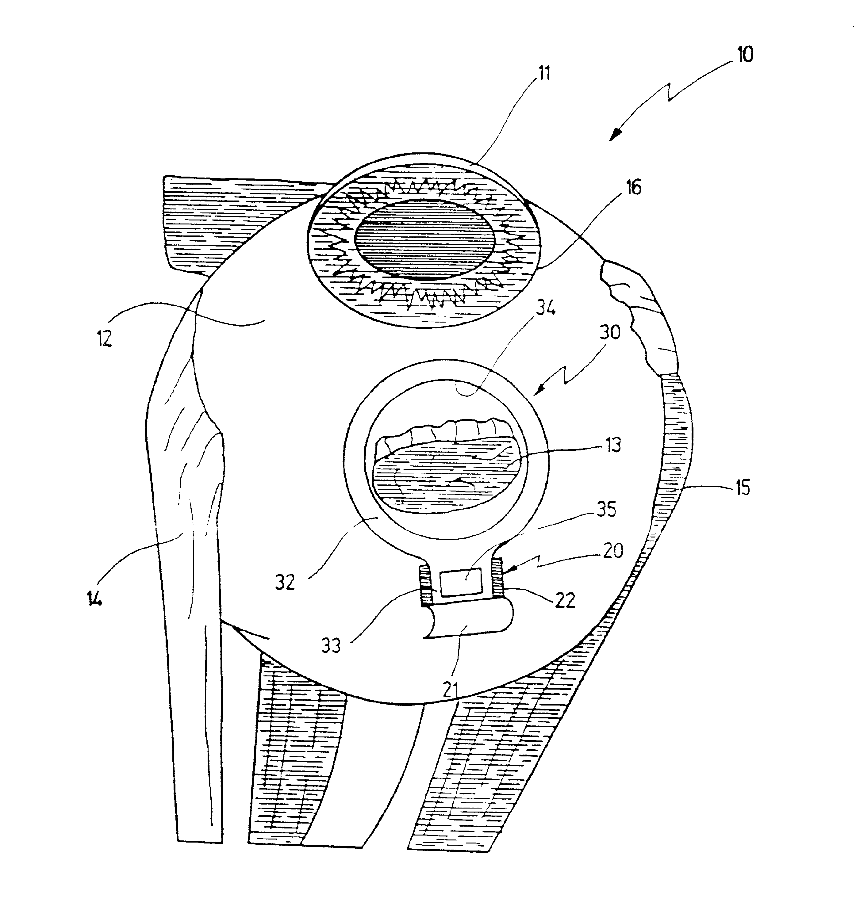
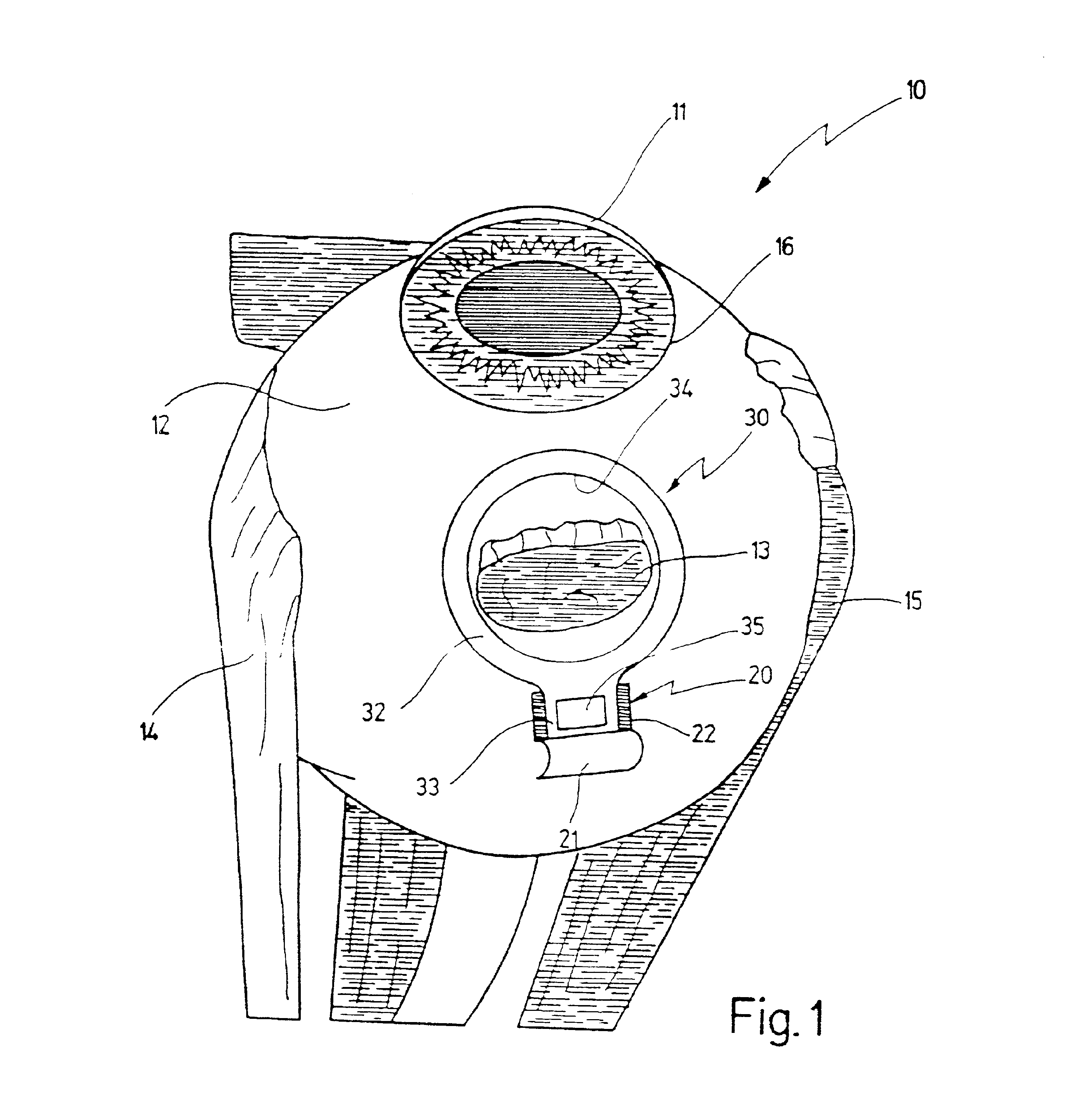
In FIGS. 1 and 6 an eyeball into which an implant according to the present invention shall be introduced, is designated as a whole by 10. Eyeball 10, at its front side, has a cornea 11 and, further, a sclera 12. The limbus corneae, i.e. the rim of cornea 11, is designated by 16 in FIG. 1. Moreover, FIG. 1 shows lateral eye muscles 14 and 15.

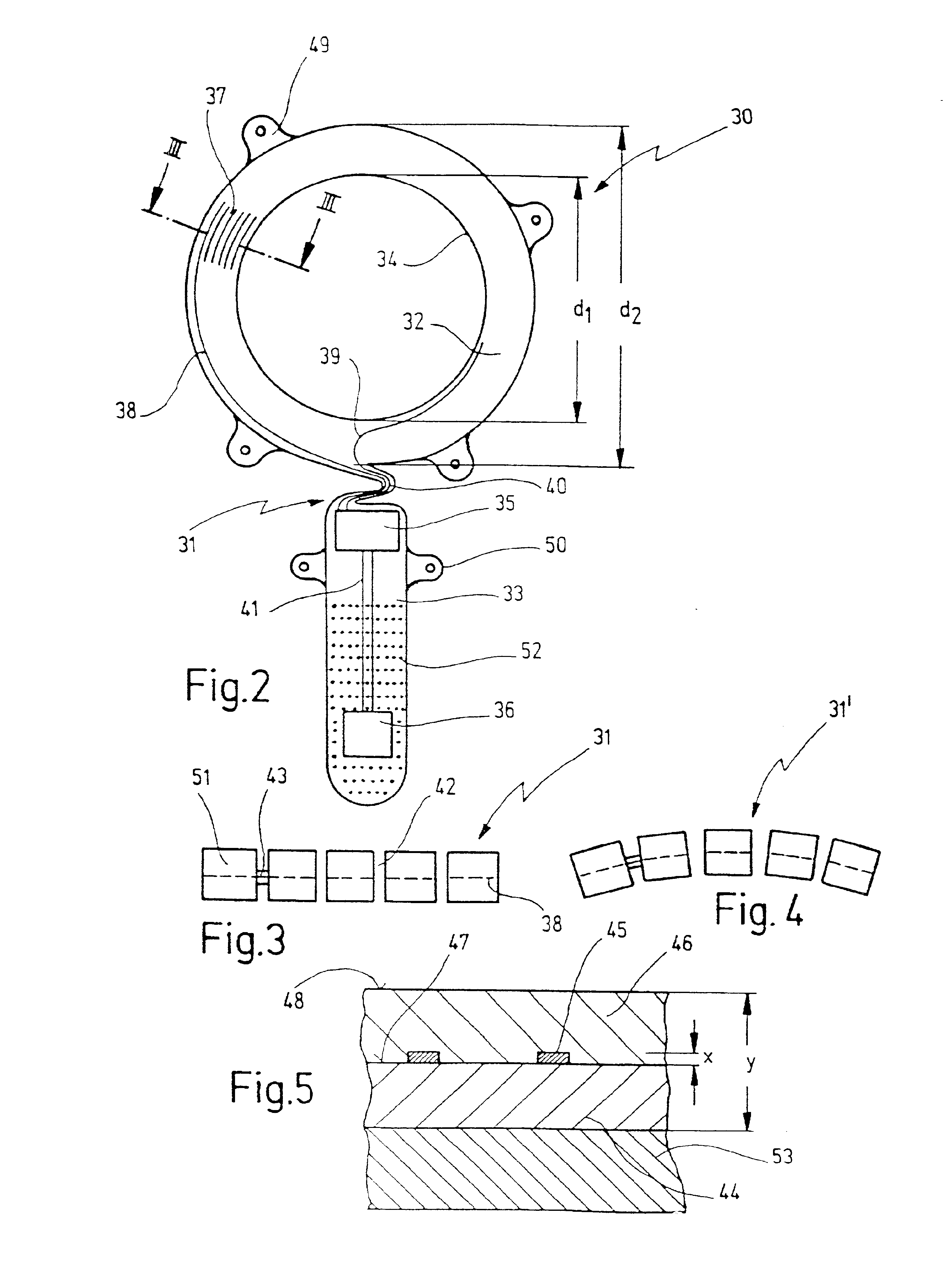
At the front portion of eyeball 10, lateral eye muscle 13 was severed by a cut. A retina implant according to the present invention, being designated as a whole by 30, has an annular portion 32 and an extension 33 adjoining the latter. A chip for subretinal implantation is located at the outer terminal end of extension 33, as may be seen in further detail in FIG. 2. FIG. 1 shows that the retina implant was positioned around lateral eye muscle 13 with its annular portion 32 and was pushed into the subretinal space with its flat extension 33 through a sclera incision 20.

The design and the manufacture of the retina implant will be described hereinaf...


PUM


Abstract

A retina implant including a chip adapted to be implanted into the interior of eye in subretinal contact with the retina. The chip has a plurality of pixel elements on a side thereof facing the lens for receiving an image projected into the retina and a plurality of electrodes for stimulating retina cells. The implants further includes a receiver coil for inductively coupling thereinto electromagnetic energy. The receiver coil coupled to a means for converting an alternating voltage induced into the receiver coil in a direct voltage suited for supplying the chip. The receiver coil is configured as a component separate from the chip, and for being positioned on the eye ball outside the sclera. The chip is connected to the receiver coil via a connecting lead which, in the implanted condition interconnects the interior and the exterior of the eye ball.

Description

FIELD OF THE INVENTIONThe invention relates to a retina implant having a chip for subretinal implantation, and comprising a receiver coil for inductively coupling thereinto electromagnetic energy, the coil being connected to means for converting an alternating voltage induced into the receiver coil into a direct voltage suited for supplying the chip.The invention, further, is related to a method for manufacturing a retina implant as specified before.Implants of that kind are generally known.BACKGROUND OF THE INVENTIONRecently, retina implants have been developed that are intended to be used for the treatment of patients whose viewing ability has gone lost entirely or in part due to retinal defects. As a matter of principle, a light-sensitive chip shall be implanted into the subretinal space below the retina. The chip is provided with a plurality of pixel elements receiving an image projected on the retina through the still intact lens of the eye, for converting same into electrical ...

Claims


Application Information

Patent Timeline
IPC IPC(8): A61F2/14A61F9/08
CPCA61F2/14A61F9/08A61N1/3787A61N1/0543
Inventor NISCH, WILFRIEDSTETT, ALFREDSCHUBERT, MARKUSGRAF, MICHAELGRAF, HEINZ GERHARDHAMMERLE, HUGOZRENNER, EBERHARTSTELZLE, MARTINSACHS, HELMUT
Owner RETINA IMPLANT
Why Eureka
Try Eureka