Light-emitting diode arrangement

a technology of light-emitting diodes and arrangements, applied in the direction of lighting support devices, mobile visual advertising, instruments, etc., to achieve the effect of reducing the cost of technological manufacturing

Inactive Publication Date: 2005-02-01
OSRAM OPTO SEMICONDUCTORS GMBH
View PDF22 Cites 171 Cited by
  • Summary
  • Abstract
  • Description
  • Claims
  • Application Information

AI Technical Summary

Benefits of technology

The LED arrangement of the present invention can preferably have its printed circuit board applied on a highly thermally conductive partial surface region of a device housing or of an automobile chassis or the like. Advantageously, the device housing or the automobile chassis thereby acts as cooling member. Among other things, this leads to a lower technological manufacturing outlay and to a weight-saving. Thus, the thermally conductive partial surface region serves as the cooling member in the present invention.

Problems solved by technology

Further, the printed circuit board should be as thin as possible since the plastic material of which it is constructed usually conducts heat poorly.

Method used


Image

  • Light-emitting diode arrangement
  • Light-emitting diode arrangement
  • Light-emitting diode arrangement

Examples


Embodiment Construction

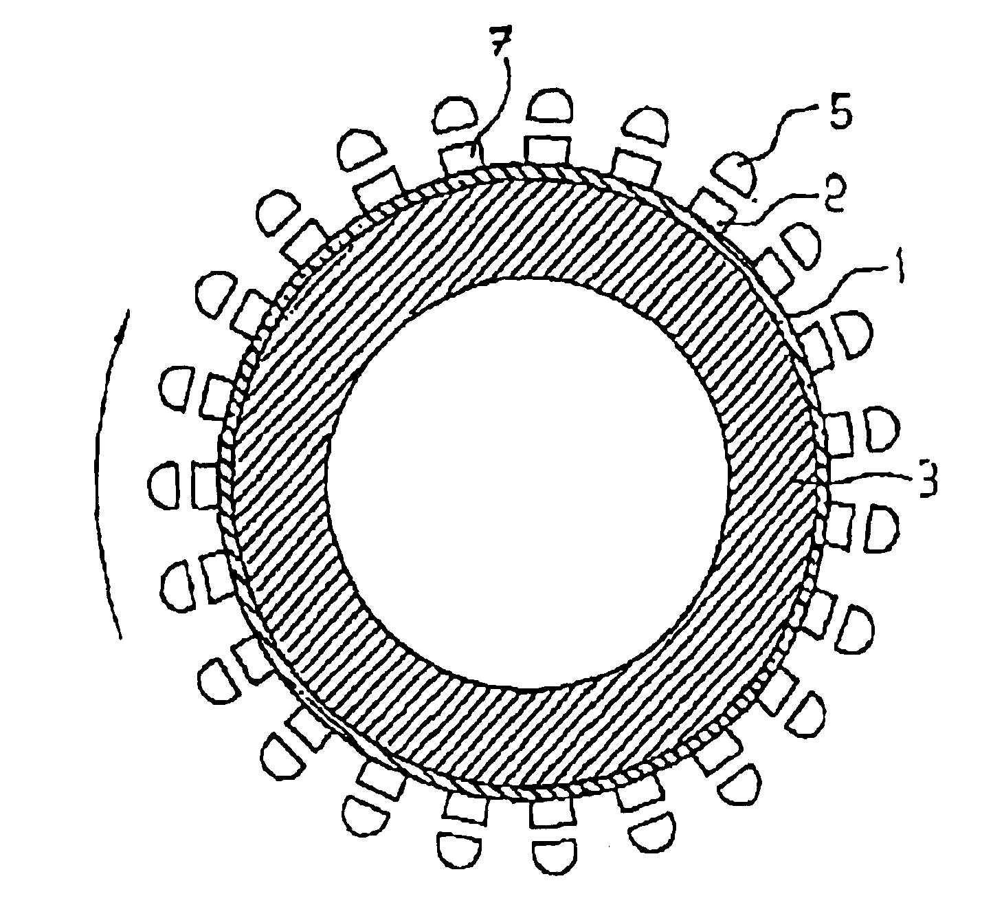
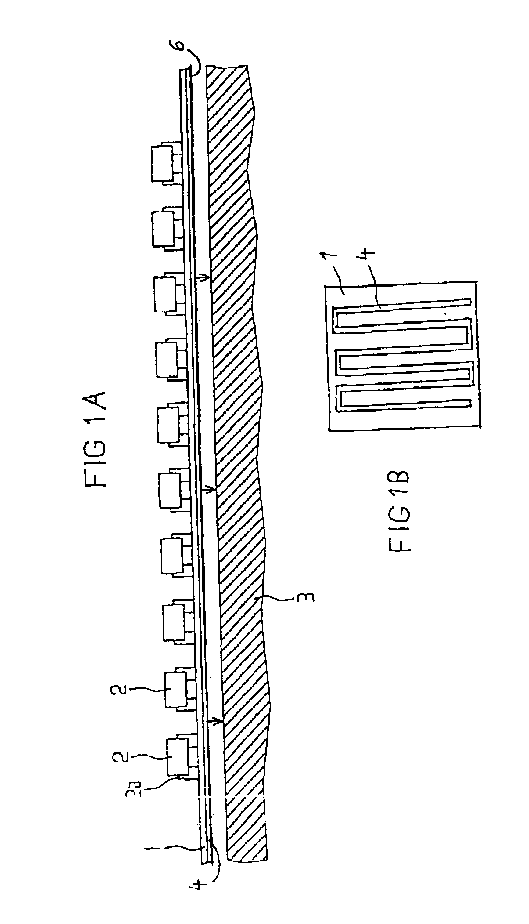
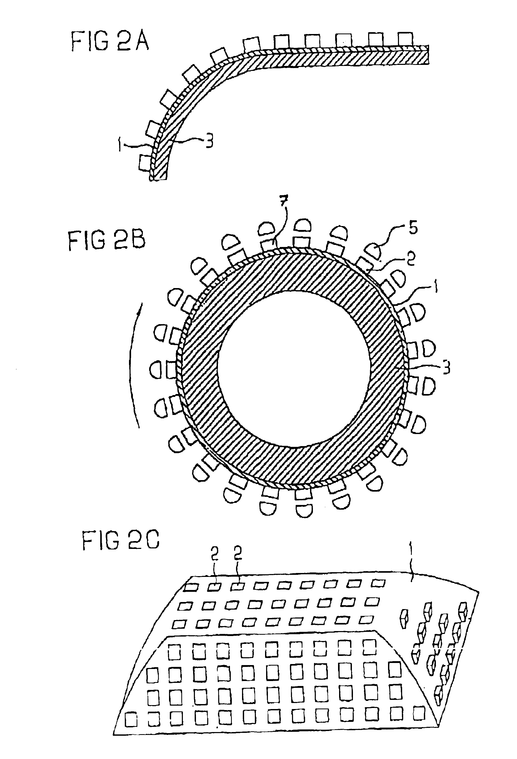
The embodiment of the present invention shown in FIG. 1A contains a printed circuit board 1 on which a plurality of preferably surface-mounted LEDs 2 are applied. In a known way, the printed circuit board 1 thereby forms a circuit that comprises terminal surfaces for the mounting of the LEDs at defined locations. These terminal surfaces are provided, for example, with lands for soldering in an automatic surface mount device (SMD) equipping unit, and the LEDs 2 have their electrical contacts 2a soldered to these terminal surfaces in a subsequent mounting step.

The printed circuit board 1 can be a rigid printed circuit board, such as type FR4, and constructed of an epoxy resin material. However, it can also be a flexible printed circuit board such as an above-described flex board. The printed circuit board 1 is laminated onto a cooling member 3 with a thermally conductive adhesive 6, a thermally conductive paste 6 or a thermally conductive film 6, said cooling member 3 being composed o...


PUM


Abstract

An LED array surface-mounted on a circuit board and applied to a cooling member, such that any generated heat is optimally eliminated. The cooling member can be in any desired shape so that motor vehicle lights, such as blinkers, can be adapted to the outside contour of the vehicle. For a rotating light, the circuit board can be applied around a cooling member fashioned as a hollow cylindrical member which is adapted to rotate.

Description

BACKGROUND OF THE INVENTION1. Field of the InventionThe present invention is directed to LED (light emitting diode) arrangements. In particular, the present invention is directed to LED arrangements that can be built into a lamp housing or located in exterior lights of motor vehicles.2. Brief Discussion of the Related ArtIn the field of exterior and interior illumination of motor vehicles, light-emitting diodes (LEDs) are being increasingly used instead of conventional incandescent bulbs, particularly for tail lights and brake lights, since LEDs have a longer service life, a better efficiency in the conversion of electrical energy into radiation energy in the visible spectral range and, connected therewith, a lower heat emission and a lower space requirement overall.EP 0 253 224 discloses a method for the manufacture of a light with light-emitting diodes. The light to be manufactured comprises a soft plastic film on whose upper side a copper lamination is applied and a plurality of ...

Claims


Application Information

Patent Timeline
Patent Type & Authority Patents(United States)
IPC IPC(8): F21V31/03F21V29/00F21V31/00F21S8/00F21S8/10G09F21/00G09F13/22G09F21/04H01L33/00H05K3/00F21V19/00F21S8/04F21V29/74F21W101/12F21W101/14F21Y115/10H01L33/64
CPCF21V29/74F21S48/328F21S48/337F21V29/004G09F13/22G09F21/04H01L33/64H05K3/0061F21S48/215F21S10/06F21W2111/00F21Y2101/02H05K2201/10106Y10S362/80H01L2924/0002H01L2924/00F21S43/14F21S45/48F21Y2115/10
Inventor ARNDT, KARLHEINZWAITL, GUENTERBOGNER, GEORG
Owner OSRAM OPTO SEMICONDUCTORS GMBH
Why Eureka
Try Eureka