

Rotary machine having bypath magnetic path blocking magnetic barrier
a rotary machine and magnetic barrier technology, applied in the direction of synchronous motors, magnetic circuit rotating parts, magnetic circuit shape/form/construction, etc., can solve the problems of insufficient reduction, insufficient increase of xd/xq, insufficient increase of produced torque, etc., to achieve the effect of prolonging the travel distance of one charging of an electrical vehicl
- Summary
- Abstract
- Description
- Claims
- Application Information
AI Technical Summary
Benefits of technology
Problems solved by technology
Method used
Image

Examples
second embodiment
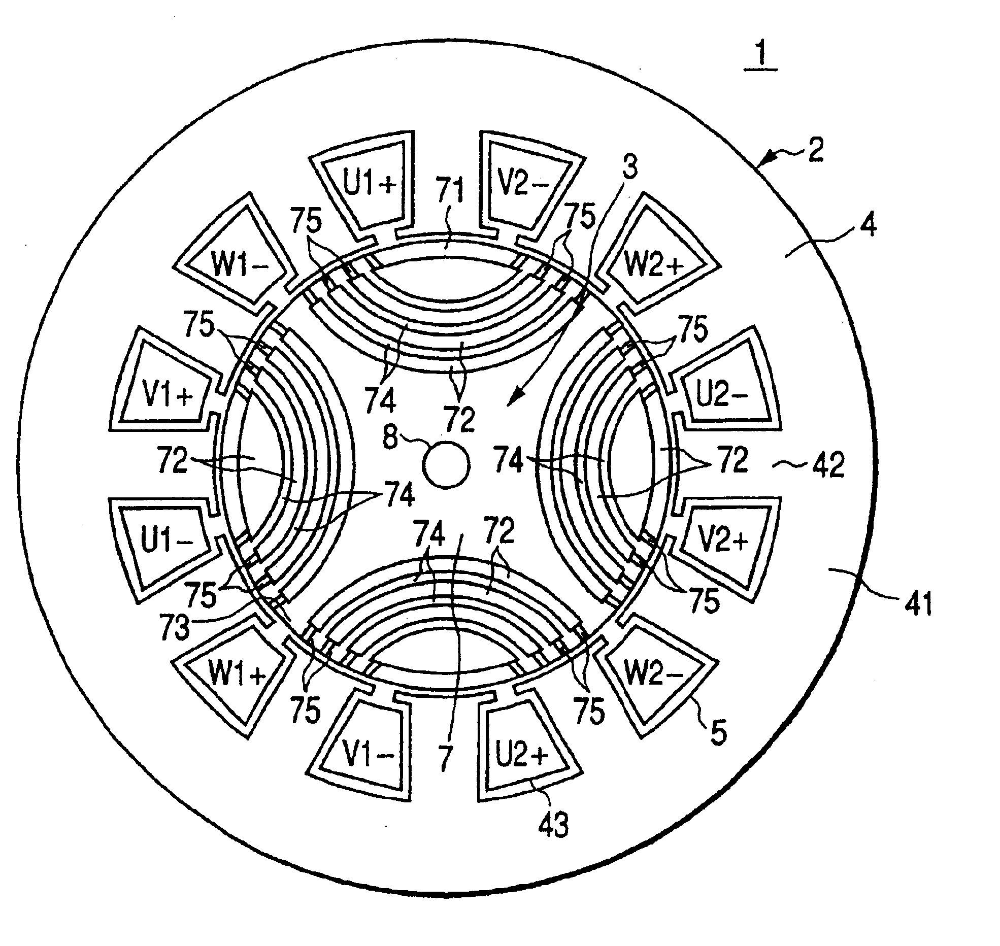
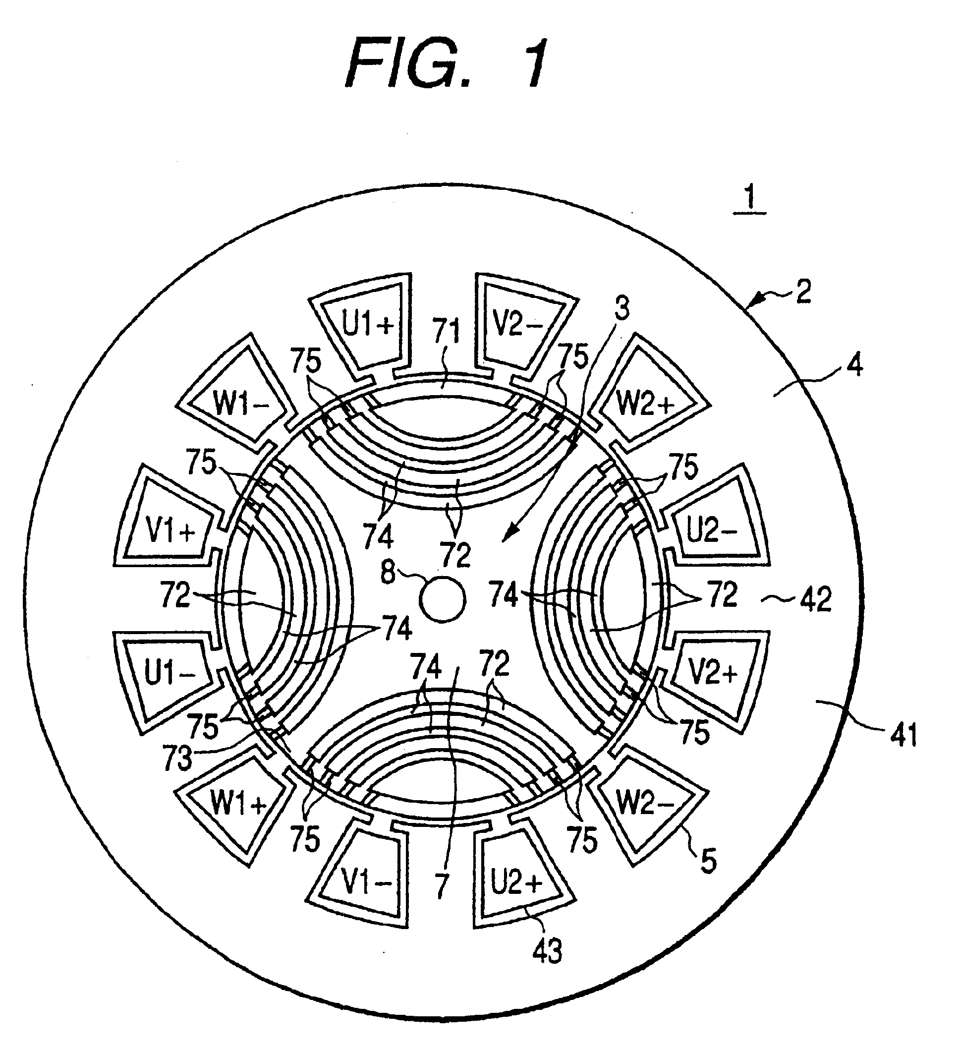
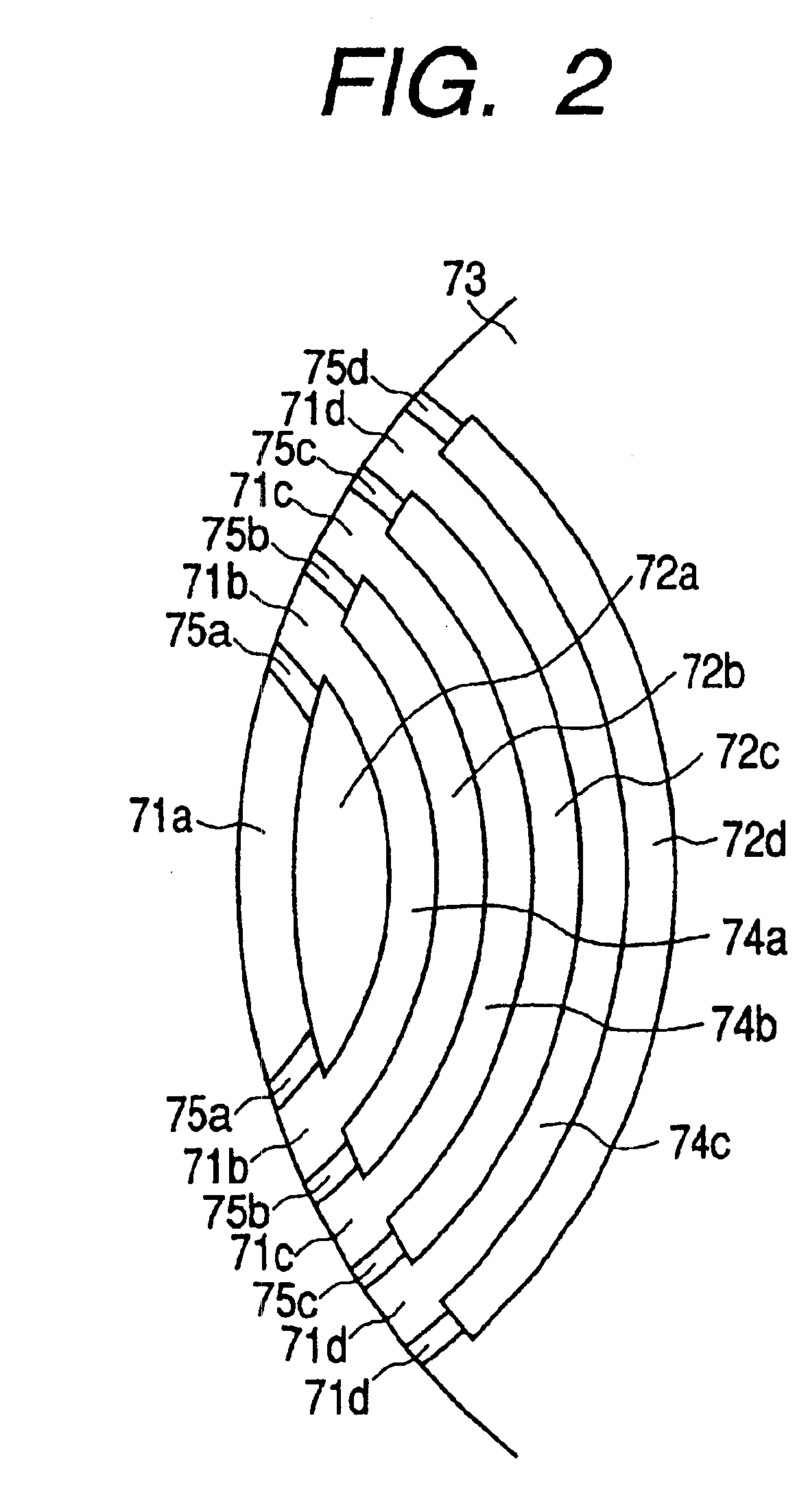
Next, the constitution and operation of the rotary machine of the present invention will be explained with reference to FIGS. 8 and 9.
FIG. 8 is a cross sectional view showing the constitution of the rotary machine of the second embodiment of the present invention and FIG. 9 is an enlarged view of the essential section shown in FIG. 8. The same numerals as those shown in FIGS. 1 and 2 indicate the same parts.
The characteristic of the reluctance motor of this embodiment is that non-magnetic part concavities 76 are installed in the peripheral part of the non-magnetic parts 75 positioned in the outer periphery of the reluctance type rotary machine. According to this embodiment, for example, the part to be non-magnetized of a material having a ferromagnetic tissue is heated at the austenite critical temperature or higher and then cooled or heated and fused at the melting point or higher and then cooled and solidified, thereby a rotor iron core that the ferromagnetic part and non-magnetic...
third embodiment
Next, the constitution and operation of the rotary machine of the present invention will be explained with reference to FIGS. 10 and 11.
FIG. 10 is a cross sectional view showing the constitution of the rotary machine of the third embodiment of the present invention and FIG. 11 is a process diagram showing the manufacturing process of a rotor of this embodiment. The same numerals as those shown in FIGS. 1 and 2 indicate the same parts.
The characteristic of the reluctance motor of this embodiment is that permanent magnets 6 are arranged in a part of the rotor. By doing this, the defects of the reluctance type rotary machine against a permanent magnet rotary machine, for example, small torque and a low power factor can be improved.
In FIG. 10, windows for housing the permanent magnets 6 are press-cut in the rotary iron core 7 having a material that the magnetic part and non-magnetic part coexist and the permanent magnets 6 are housed in the windows. The length of each permanent magnet 6...
PUM
 Abstract
Description
Claims
Application Information