Electrical machine stator and rotor

a technology of stator and rotor, which is applied in the direction of dynamo-electric machines, magnetic circuit rotating parts, magnetic circuit shape/form/construction, etc., can solve the problems of parasitic torque, reduced performance, and reduced efficiency of electrical machines, so as to improve the efficiency of electrical machines

Inactive Publication Date: 2005-02-01
HOGANAS AB
View PDF13 Cites 42 Cited by
  • Summary
  • Abstract
  • Description
  • Claims
  • Application Information

AI Technical Summary

Benefits of technology

An object of the present invention is to provide a stator or a rotor for an electrical machine which benefits from the use of the single tooth geometry and results in an improved efficiency of the electrical machine.

Problems solved by technology

However, for an induction machine, the single tooth winding can result in a reduced performance due to increased content of MagnetoMotive Force (MMF) harmonics compared to a traditional distributed overlapping winding design.
These higher order harmonics couples to the rotor and result in increased losses, parasitic torques, etc.
Said stator reduces harmonics, but can result in a reduction of performance compared to the traditional distributed overlapping winding design.

Method used


Image

  • Electrical machine stator and rotor
  • Electrical machine stator and rotor
  • Electrical machine stator and rotor

Examples


Embodiment Construction

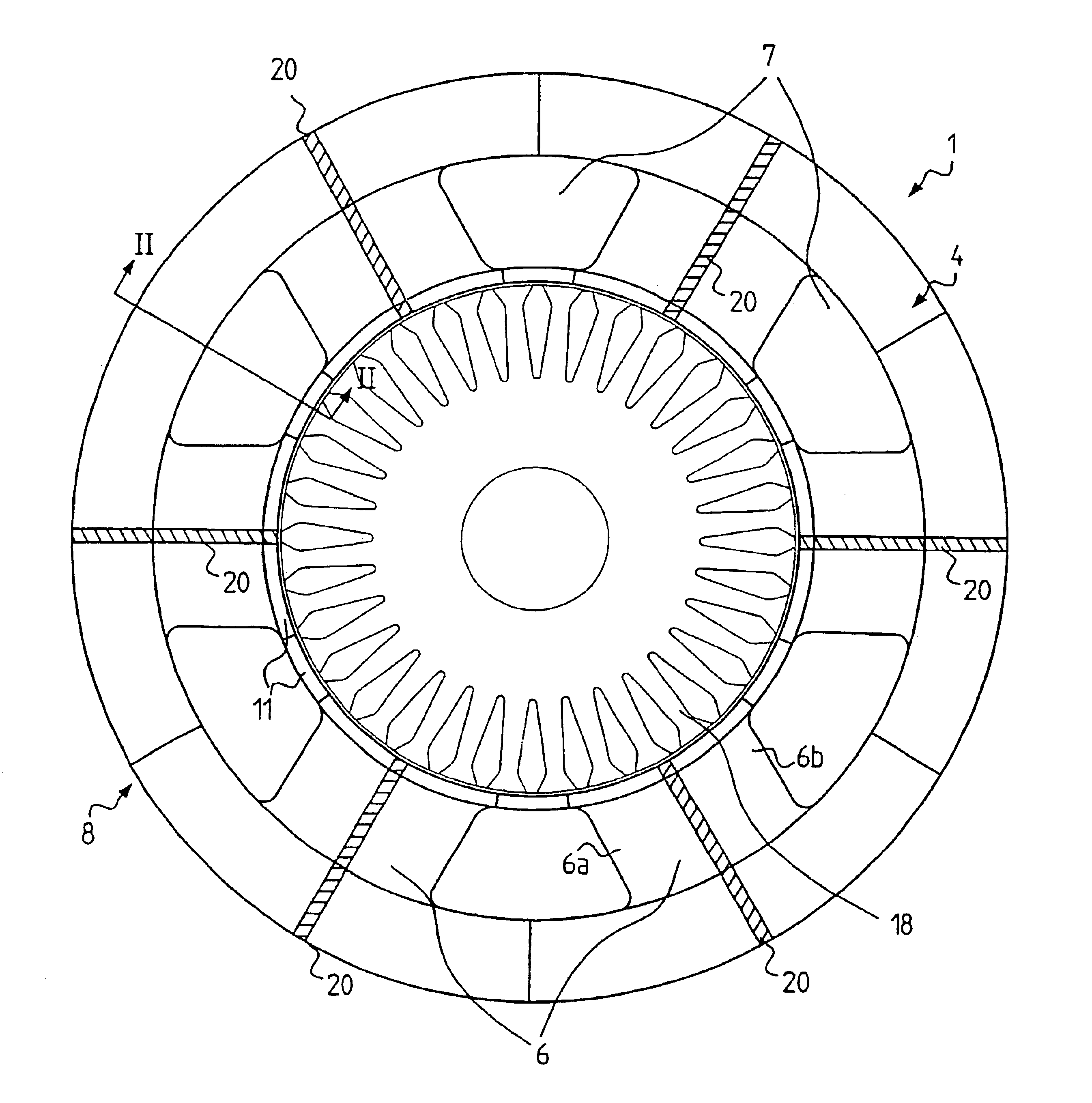
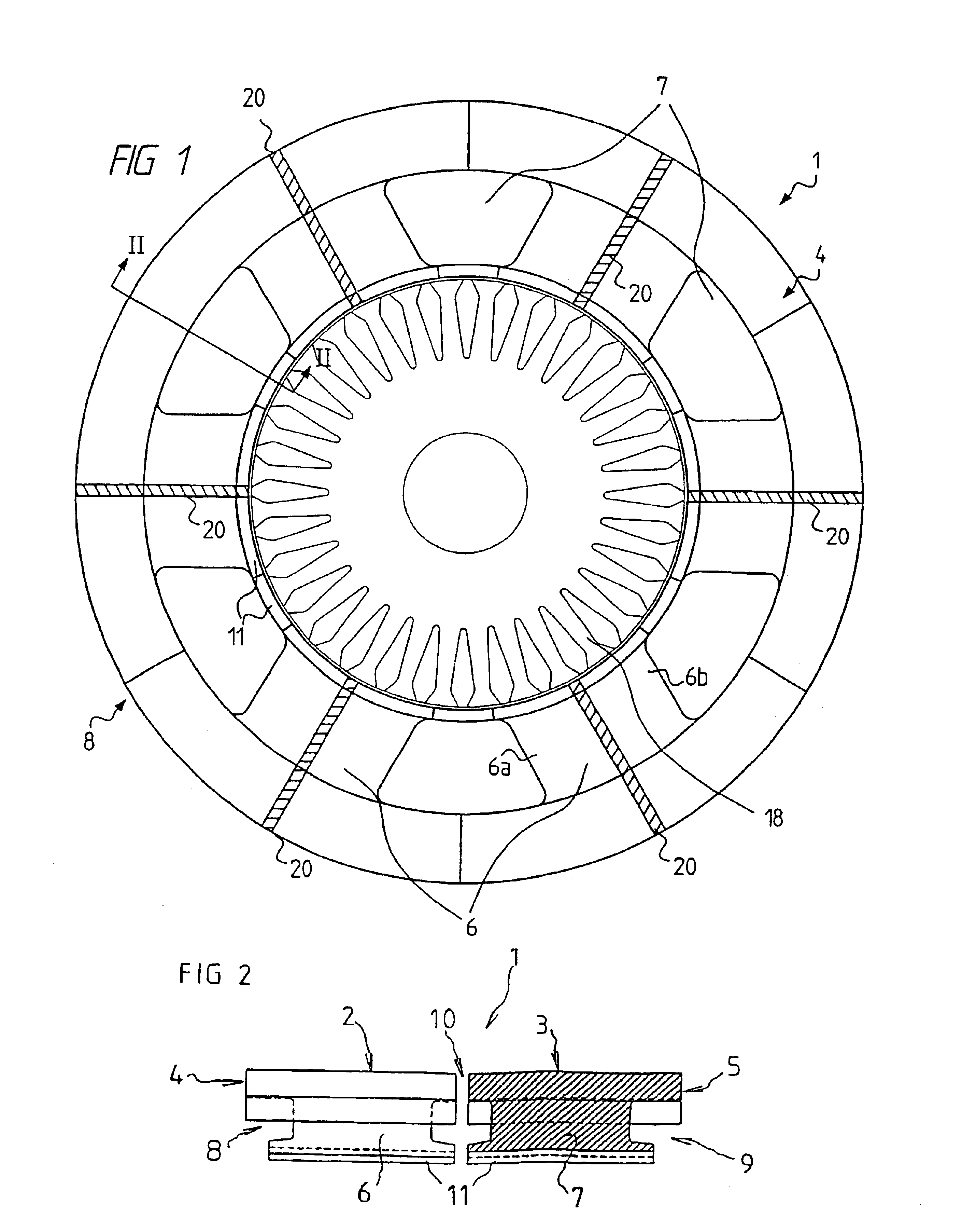
Referring to FIGS. 1 and 2, a stator 1 of an induction motor is illustrated as having two axially separated stator sections 2 and 3. Each one of the stator sections has a yoke section 4 and 5, respectively, adjoining six circumferentially separated, radially extending teeth 6 and 7, respectively.

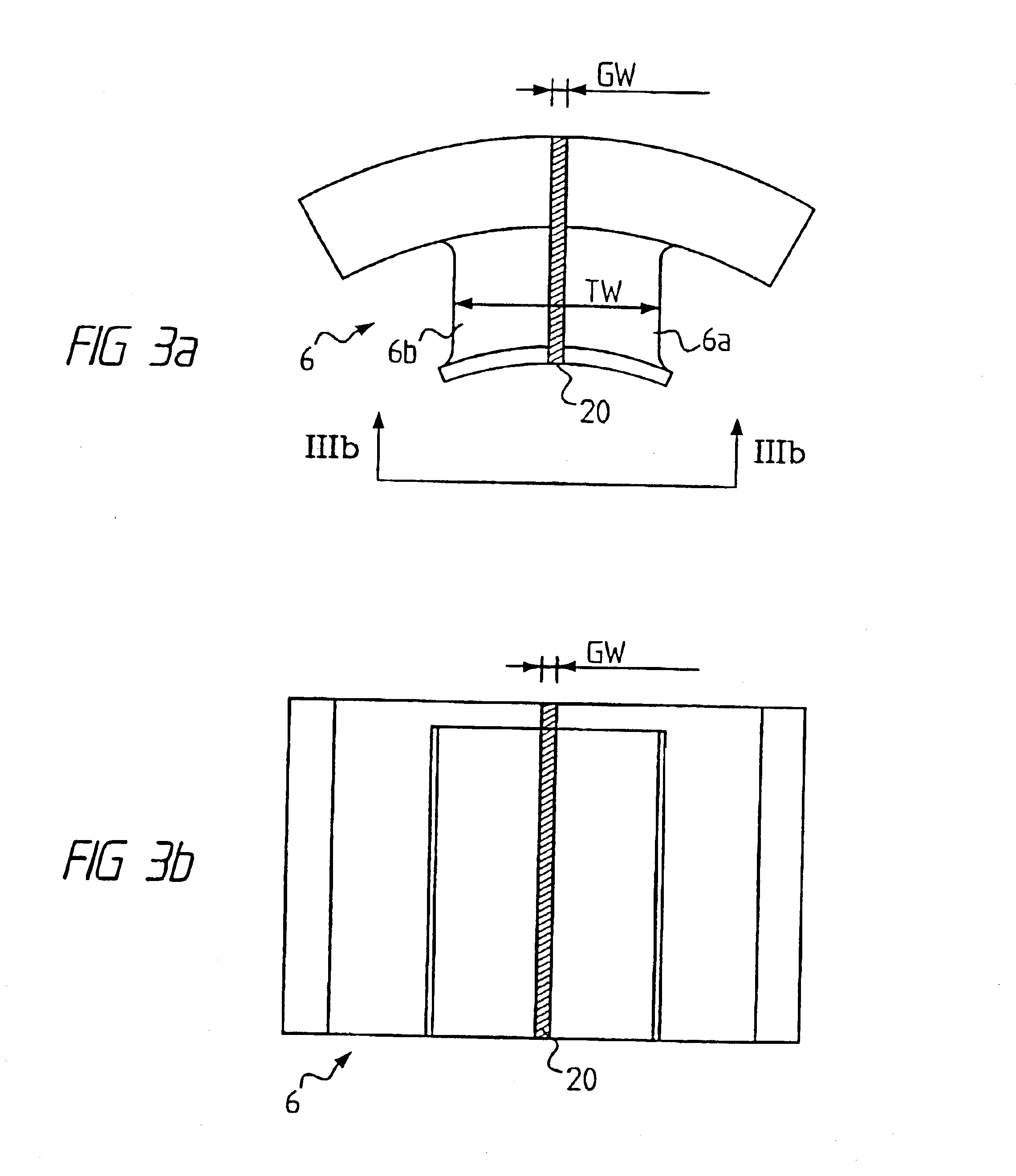
Each tooth 6 is preferably divided into two portions 6a,b which are circumferentially separated by a gap 20. In the preferred embodiment the gap 20 also extends through the yoke section 4 that is integrated with the tooth 6. However, the gap 20 does not necessarily extend through said yoke section 4, especially if the yoke section 4 and the tooth 6 are not integrated. The teeth 7 have a corresponding shape.

Further, each tooth 6 and an adjoining part of the corresponding yoke section 4 form a separate unit or segment 8. Similarly, each tooth 7 and an adjoining part of the corresponding yoke section 5 form a separate unit or segment 9.

The yoke sections 4 and 5 are physically phase shifted by 1...


PUM


Abstract

A stator or a rotor for an electrical machine comprises a plurality of circumferentially separated, radially extending teeth, wherein each tooth having a single winding and is provided with an axially and radially extending reluctance barrier to increase the reluctance of each tooth regarding propagation of a magnetic field not interacting with the winding of said tooth.

Description

TECHNICAL FIELD OF THE INVENTIONThe present invention is generally related to electrical machines and more specifically to a stator or a rotor for an electrical machine.BACKGROUND OF THE INVENTIONConventionally, the stator assembly of an electrical machine has a stator core formed of a stack of steel laminations. As an alternative to the use of steel laminations, the stator core may be formed from iron powder, as exemplified by U.S. Pat. No. 4,947,065 disclosing a stator moulded in one-piece, and by International Patent Application WO95 / 12912 disclosing a stator comprising a plurality of separate and substantially identical parts.By its very nature any compacted, non-sintered material will not be fully dense. This means that soft iron powder currently available will have permeabilities that are lower than the permeabilities obtainable with steel laminations. However, magnetic powder composites could offer advantages such as isotropic magnetic behaviour, reduction in iron losses at h...

Claims


Application Information

Patent Timeline
Patent Type & Authority Patents(United States)
IPC IPC(8): H02K1/22H02K1/14H02K1/24H02K1/16H02K1/18H02K16/04
CPCH02K1/24H02K1/148H02K1/14H02K1/22
Inventor JACK, ALAN G.MECROW, BARRIEKROGEN, OYSTEIN
Owner HOGANAS AB
Why Eureka
Try Eureka