
Photo fixer and thermal printer having the same

a technology of thermal printer and fixer, which is applied in the direction of inking apparatus, recording apparatus, instruments, etc., can solve the problems of destroying the coloring ability of the fixer, the use of light sources including mercury has been recently reconsidered, and the shutter mechanism has a considerable dimension, so as to achieve efficient and easy control of the amount of fixing rays

Inactive Publication Date: 2005-02-01
FUJIFILM CORP +1
View PDF6 Cites 4 Cited by
  • Summary
  • Abstract
  • Description
  • Claims
  • Application Information

AI Technical Summary

Benefits of technology

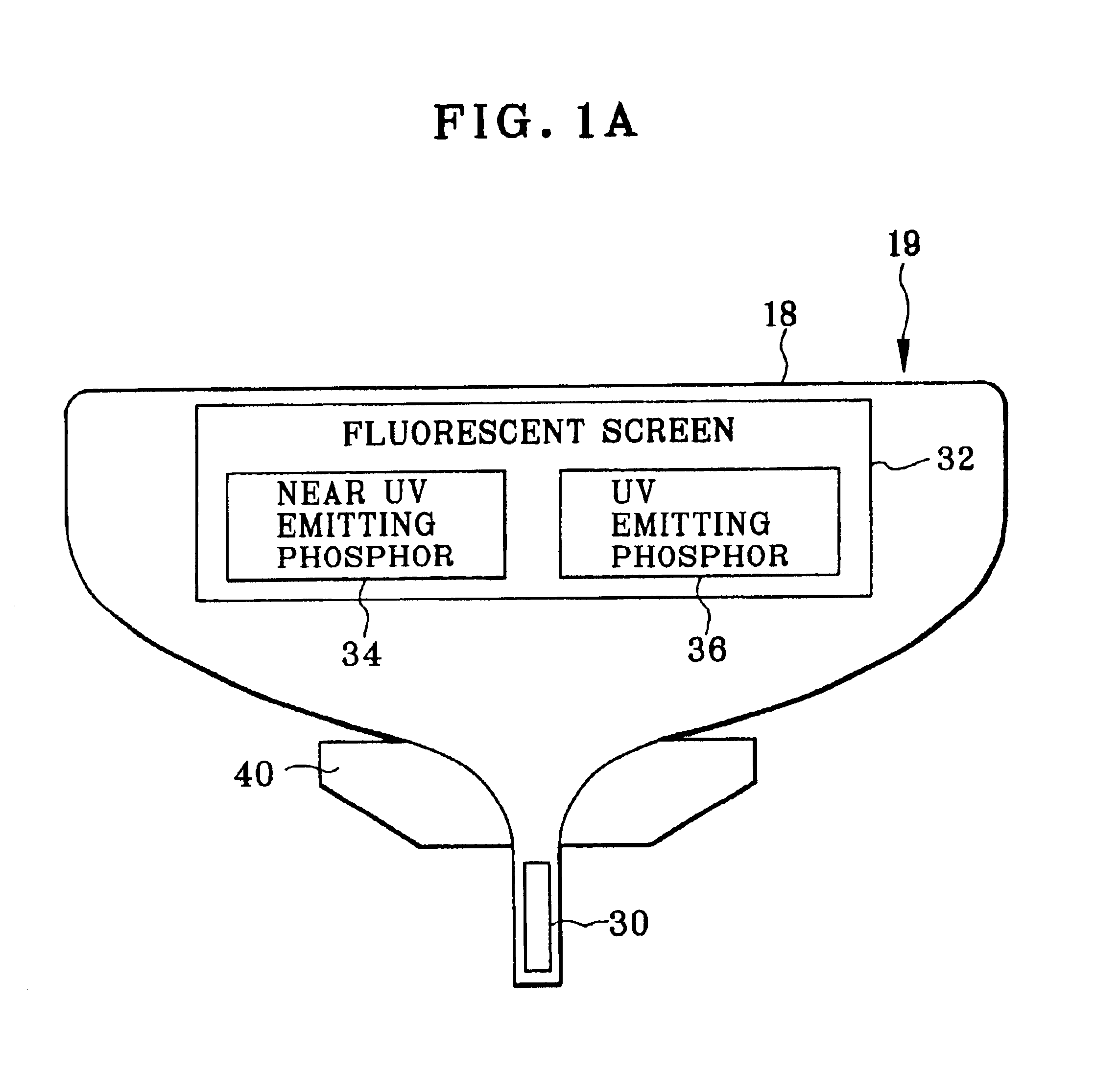
The present invention provides a photo fixer and thermal printer with the same, which allows for efficient and easy control of the amount of fixing rays without the need for a shutter. The photo fixer includes an electron radiation source, a fluorescent screen, and an electromagnetic ray applying surface for applying the electromagnetic rays to the recording material. The recording material is thermosensitive and has multiple coloring layers that have different photo fixability ranges. The fluorescent screen has phosphor materials that emit the near ultraviolet rays or ultraviolet rays of the first and second wavelength ranges. The thermal printer includes a thermal head for recording images and the photo fixer for fixing the images on the recording material. The recording material is fed by a feeder and the photo fixer includes an electron deflecting unit for selectively emitting the electromagnetic rays. The technical effects of the invention include efficient and easy control of the fixing rays, improved quality in printing, and reduced costs.

Problems solved by technology

The two coloring layer being not near to the support have such fixability that its coloring ability is destroyed when near ultraviolet or ultraviolet rays is applied to the recording paper.
The use of light sources including mercury has been recently reconsidered because waste mercury contaminates the environment.
However, a problem arises in that the shutter mechanism has a considerable dimension and is inconsistent to reduction of the size of the color thermal printer.
It is very difficult to set the xenon lamp at a desired intensity of light.
Thus, high quality in printing is hard to obtain due to a difference between the fixing states of the coloring layers.

Method used


Image

  • Photo fixer and thermal printer having the same
  • Photo fixer and thermal printer having the same
  • Photo fixer and thermal printer having the same

Examples


Embodiment Construction

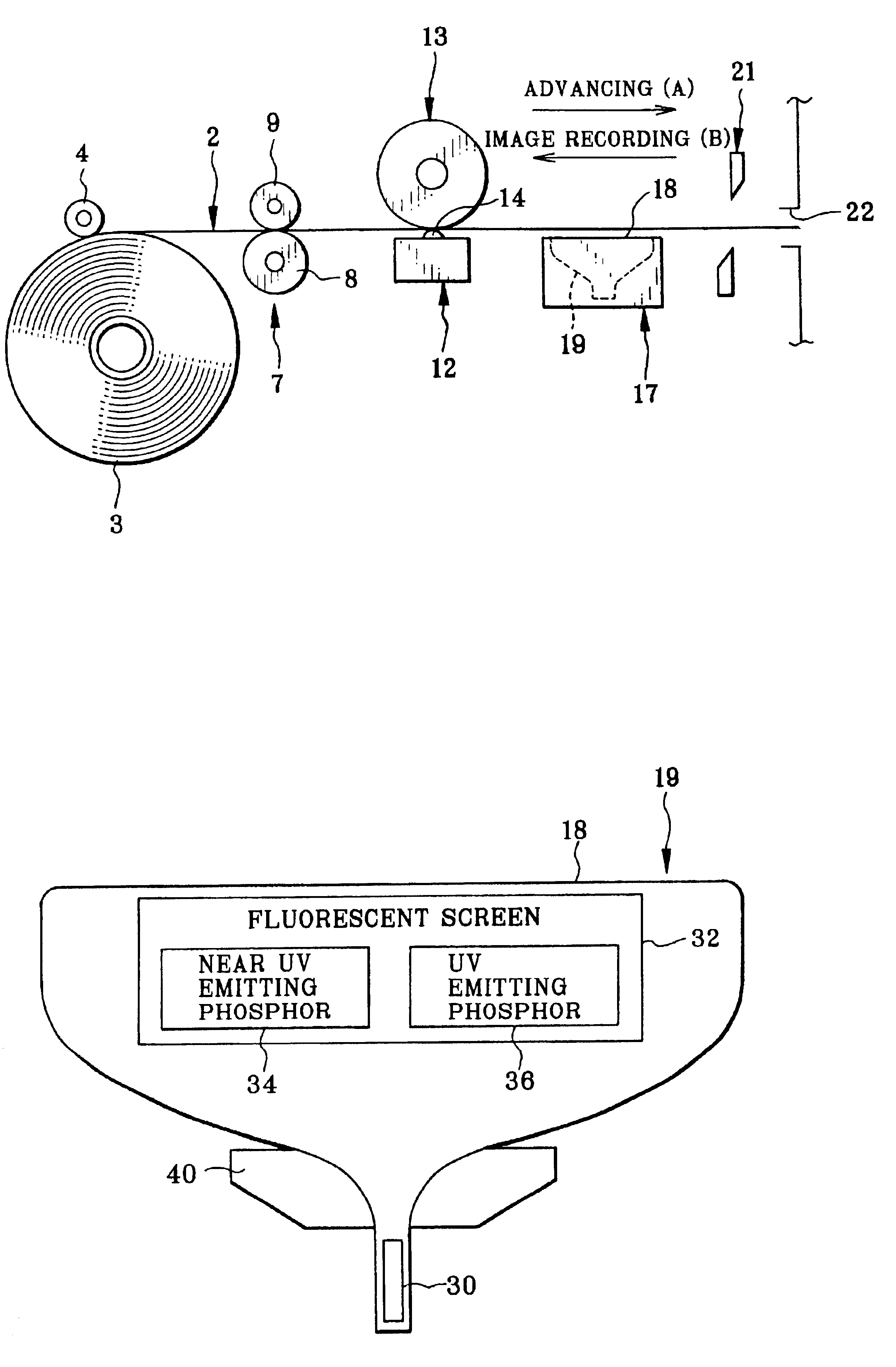
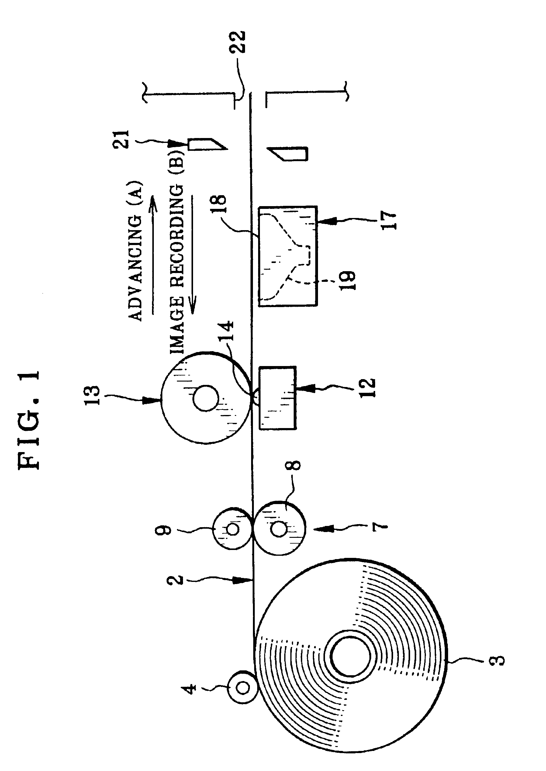
view in side elevation, illustrating a Braun tube as a photo fixer in the printer;

[0022]FIG. 2 is a perspective illustrating the photo fixer together with a color thermosensitive recording material;

[0023]FIG. 3 is a graph illustrating a relationship between the light output amount and the grid voltage of the Braun tube;

[0024]FIG. 4 is a perspective illustrating another preferred photo fixer constituted by a Braun tube in a long shape.

DETAILED DESCRIPTION OF THE PREFERRED EMBODIMENT(S) OF THE PRESENT INVENTION

[0025]In FIG. 1, a color thermal printer of the present invention is illustrated. A color thermosensitive recording material 2 in a continuous shape is used. A recording material roll 3 is initially prepared as a roll of the recording material 2, and is set in the thermal printer.

[0026]A supply roller 4 contacts an outermost turn of the recording material roll 3. A supply motor (not shown) drives the supply roller 4 to rotate. When the supply roller 4 rotates in the counterclock...


PUM


Abstract

A color thermal printer includes a photo fixer, which is constituted by a Braun tube. An electron beam gun emits electron. A fluorescent screen is excited by the electron, for generating near ultraviolet rays or ultraviolet rays. An image on thermosensitive recording material is fixed by application of the near ultraviolet rays or ultraviolet rays.

Description

BACKGROUND OF THE INVENTION[0002]1. Field of the Invention[0003]The present invention relates to a photo fixer and thermal printer having the same. More particularly, the present invention relates to a photo fixer and thermal printer having the same, in which a control of an amount of fixing rays can be efficient and easy, and no shutter for shielding fixing rays is required.[0004]2. Description Related to the Prior Art[0005]A color thermal printer is used with color thermosensitive recording paper, and produces full-color prints. The recording paper includes a support and at least three thermosensitive coloring layers overlaid thereon. Among the three, a coloring layer which is positioned the farther from the support has a higher heat sensitivity, and colorable in response to lower heat energy. The two coloring layer being not near to the support have such fixability that its coloring ability is destroyed when near ultraviolet or ultraviolet rays is applied to the recording paper. ...

Claims


Application Information

Patent Timeline
Patent Type & Authority Patents(United States)
IPC IPC(8): B41J11/00B41J2/315B41J2/32
CPCB41J2/315B41J11/0015B41J2202/34
Inventor TAKI, TOMOKOKOKUBO, HIDEYUKI
Owner FUJIFILM CORP
Learn More