Time recorder

a time recorder and time recorder technology, applied in the field of time recorders, can solve the problems of difficult printing, and limited number of clock ins/outs printable on one line, so as to reduce the cost of creating time cards, the time space is not wasted, and the width of time cards is not increased.

Inactive Publication Date: 2005-02-01
SEIKO SOLUTIONS
View PDF4 Cites 1 Cited by
  • Summary
  • Abstract
  • Description
  • Claims
  • Application Information

AI Technical Summary

Benefits of technology

Specifically, in the present invention, a time card on which the clock-out information has been printed on the final print line and which is not yet taken over is inserted again. Thus, it is checked whether the card identification information has been registered with the recording unit. Clock in / out information that is not yet taken over and has been recorded relative to the card identification information is identified. The identified clock in / out information is rerecorded as clock in / out information corresponding to the card identification information on a newly inserted, unused time card. Accordingly, no manual switching operation is needed. In the same manner as in the cases of the third and fourth features, if a long time passes before takeover processing, the takeover processing can be reliably performed for the same person.
The advantages of the invention are now described. First, each different set of clock in / out information is printed on a different print line in turn. Clock in / out information can be printed regardless of the number of clock ins / outs in a day without increasing the width of the time card. Secondly, clock in / out information is updated for a new time card and so working hours, early leave, overtime hours, and so on in each given period can be totalized, calculated, and printed. Thirdly, printing can be done without preparing lines for holidays. Therefore, time space is not wasted.
Fourthly, printing and totalization of clock in / out information about the same person are carried out for each card identification information attached to each time card. Therefore, it is not necessary to enter identification information for each person. Accordingly, the cost of creating time cards can be reduced. Also, the procedure for processing information in the control unit can be made simpler. Fifthly, takeover processing can be started manually and so this takeover processing can be reliably done by the same person if takeover processing cannot be done immediately and a long time has passed.
Sixthly, where clock-out information is printed on the final print line of a time card, the user of the time card can be reliably informed by the warning unit that the takeover processing is necessary. Seventhly, if an erroneous time card is inserted during the takeover operation, the warning unit can give a notice of the effect to the user of the time card. Eighthly, the takeover processing can be started simply by reinserting a used time card. Therefore, the same person can reliably perform the takeover processing without manual operations if the takeover processing cannot be performed immediately and a long time has passed.

Problems solved by technology

However, in the method of printing clock in / out times in one day on one line as in Reference 1, because of a limitation on the printable width of each time card, the number of clock ins / outs printable on one line is limited to 2 to 6 at most.
Furthermore, where the actual working hours between clock ins and clock outs are totalized again and printed as in Reference 2, the number of clock ins / outs printable on one line is also limited and so the printing is not easy to read.
If the print font size is reduced, however, it becomes more difficult to read the printing visually.
Also, misreading occurs more frequently.
If the width of the time card itself is increased, the size of the time recorder that prints on the time card is increased, thus presenting problems.
That is, the manufacturing cost is increased.
Furthermore, lines for holidays are left as empty lines in principle, resulting in wastage.

Method used


Image

  • Time recorder
  • Time recorder
  • Time recorder

Examples


Embodiment Construction

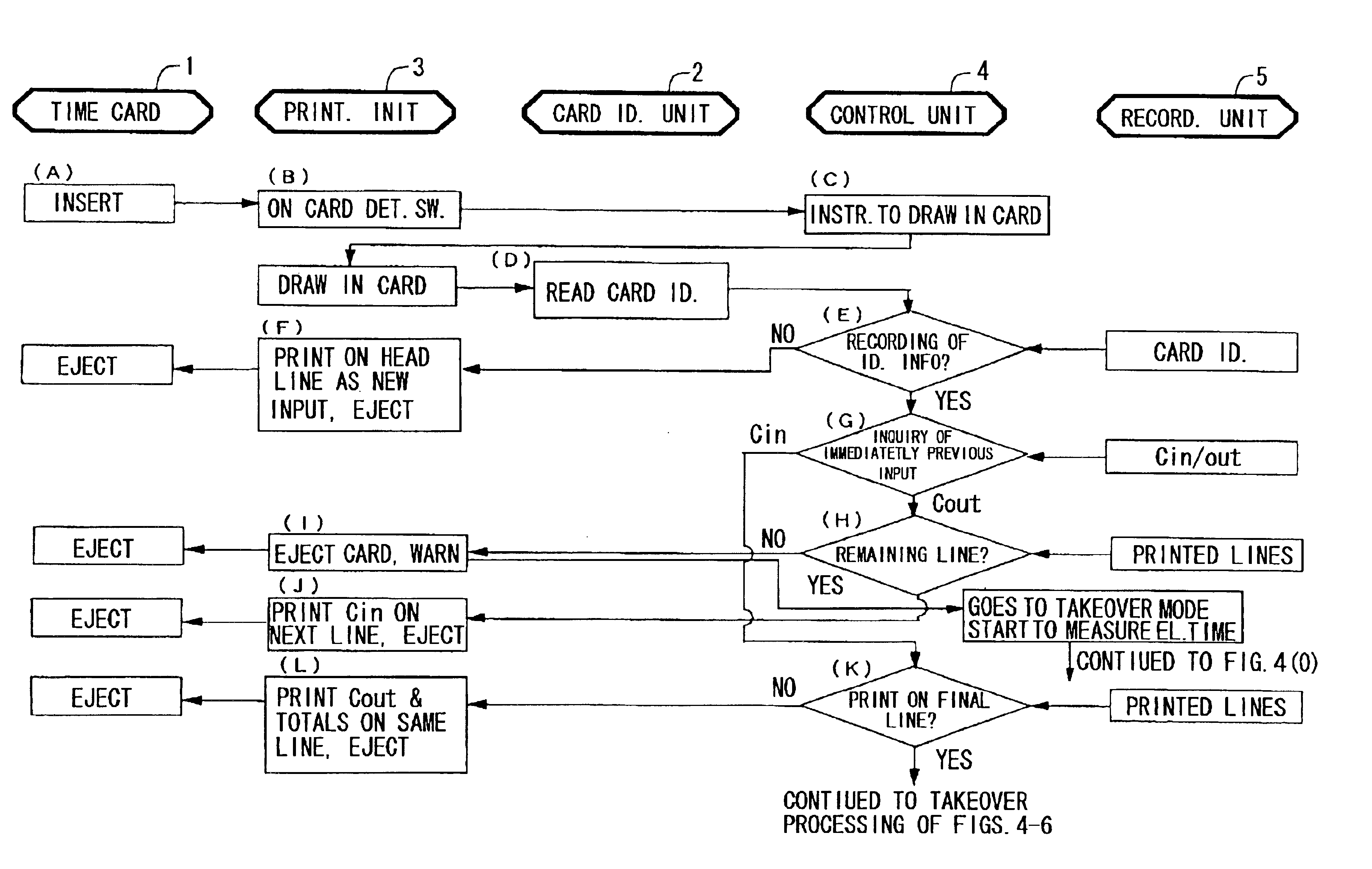
A time recorder according to the present invention is used for a time card 1 having card identification information 1a. The recorder has card identification units 2a, 2b for identifying the card identification information, a printing unit 3 for printing clock in / out information on the time card, a recording unit 5 for recording the card identification information and the clock in / out information, and a control unit 4.

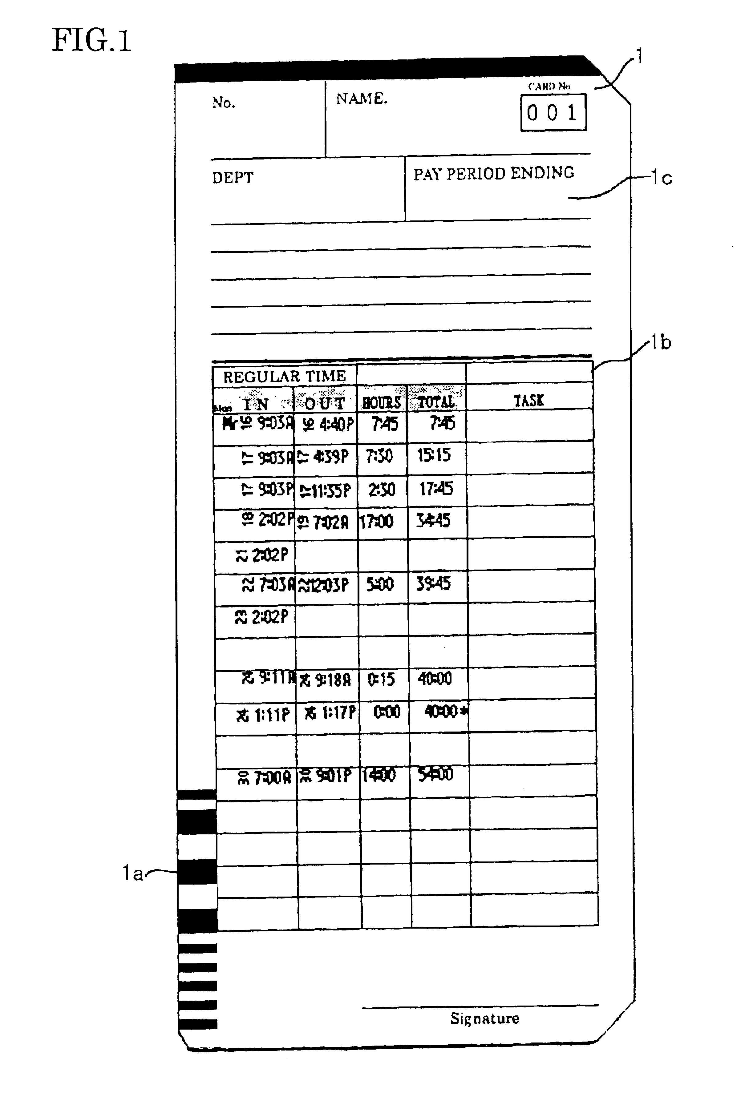
First, the time card 1 used for the time recorder according to the invention is described by referring to FIG. 1. The time card 1 consists of a vertically long cardboard. A barcode 1a that is card identification information is attached to a lower, left side portion of each such time card. Handwritten or typed columns 1c including name (NAME), belonging department (DEPT), and final day of the pay period (PAY PERIOD ENDING) are formed at higher positions. Columns 1b where clock in / out information such as clock in / out times is printed are put in the center.

In particular, f...


PUM


Abstract

A time recorder can print characters without reducing the print font size or increasing the width of a time card itself. Also, no limitations are imposed on the number of clock ins/outs per day. A control unit checks the identity of card identification information attached to the time card. The control unit instructs a printing unit to print clock in/out information in succession such that the printed line is changed for each one set of clock in/out, and records the information in a recording unit. When all the print lines are used up, clock in/out information recorded in the recording unit is taken over as card identification information on a new time card.

Description

BACKGROUND OF THE INVENTION1. Field of the InventionThe present invention relates to a time recorder to punch in and out for managing employees or the like.2. Description of the Related ArtIn the past, as a time recorder operating to punch in and out for managing employees or the like dedicated time cards have been used, based on a pay period such as a monthly, weekly, or biweekly period matched to the company's employment regulations and procedures. Printing has been done on one time card per pay period. The printing system is described in further detail by taking a time card for a monthly pay period as an example. Fifteen print lines are formed on the front side and 16 print lines on the rear side. In total, 31 print lines are formed. Daily clock in / out times are printed such that one line is assigned to one day. Where there are no ins / outs on a holiday or vacation, the blank columns are left.Therefore, where an employee repeats in and out his office several times during a period ...

Claims


Application Information

Patent Timeline
Patent Type & Authority Patents(United States)
IPC IPC(8): G07C1/06G07C1/00
CPCG07C1/06
Inventor OZAWA, KENJIYASUI, YUUKI
Owner SEIKO SOLUTIONS
Why Eureka
Try Eureka