Method and apparatus for controlling a vehicular component

a technology for occupant restraints and components, applied in the direction of child seats, pedestrian/occupant safety arrangements, instruments, etc., can solve the problems of irreparable damage to vehicles, vehicle drivers or users are often left stranded, and the system that provides remote monitoring does not provide automatic analysis and communication of problems or potential problems and recommendations to drivers, so as to reduce the cost of repairing or replacing components, the effect of increasing the value of existing sensors

Inactive Publication Date: 2005-02-01
AUTOMOTIVE TECH INT
View PDF30 Cites 142 Cited by
  • Summary
  • Abstract
  • Description
  • Claims
  • Application Information

AI Technical Summary

Benefits of technology

It is another object of the present invention to provide a new and improved method and system for diagnosing components in a vehicle and the operating status of the vehicle and alerting the vehicle's dealer, or another repair facility, via a telematics link that a component of the vehicle is functioning abnormally and may be in danger of failing.
Principal objects and advantages of this invention or other inventions disclosed herein are thus:1. To prevent vehicle breakdowns.2. To alert the driver of the vehicle that a component of the vehicle is functioning differently than normal and might be in danger of failing.3. To alert the dealer, or other repair facility, that a component of the vehicle is functioning differently than normal and is in danger of failing.4. To provide an early warning of a potential component failure and to thereby minimize the cost of repairing or replacing the component.5. To provide a device which will capture available information from signals emanating from vehicle components for a variety of uses such as current and future vehicle diagnostic purposes.6. To provide a device that uses information from existing sensors for new purposes thereby increasing the value of existing sensors and, in some cases, eliminating the need for sensors that provide redundant information.7. To provide a device which is trained to recognize deterioration in the performance of a vehicle component, or of the entire vehicle, based on information in signals emanating from the component or from vehicle angular and linear accelerations.8. To provide a device which analyzes vibrations from various vehicle components that are transmitted through the vehicle structure and sensed by existing vibration sensors such as vehicular crash sensors used with airbag systems or by special vibration sensors, accelerometers, or gyroscopes.9. To provide a device which provides information to the vehicle manufacturer of the events leading to a component failure.10. To apply pattern recognition techniques based on training to diagnosing potential vehicle component failures.11. To apply component diagnostic techniques in combination with intelligent or smart highways wherein vehicles may be automatically guided without manual control in order to permit the orderly exiting of the vehicle from a restricted roadway prior to a breakdown of the vehicle.12. To apply trained pattern recognition techniques using multiple sensors to provide an early prediction of the existence and severity of an accident.13. To utilize pattern recognition techniques and the output from multiple sensors to determine at an early stage that a vehicle rollover might occur and to take corrective action through control of the vehicle acceleration, brakes and steering to prevent the rollover or if it is preventable, to deploy side head protection airbags to reduce the injuries.14. To use the output from multiple sensors to determine that the vehicle is skidding or sliding and to send messages to the various vehicle control systems to activate the throttle, brakes and / or steering to correct for the vehicle sliding or skidding motion.

Problems solved by technology

However, vehicles perform such monitoring typically only for the vehicle driver and without communication of any impending results, problems and / or vehicle malfunction to a remote site for trouble-shooting, diagnosis or tracking for data mining.
In the past, systems that provide for remote monitoring did not provide for automated analysis and communication of problems or potential problems and recommendations to the driver.
As a result, the vehicle driver or user is often left stranded, or irreparable damage occurs to the vehicle as a result of neglect or driving the vehicle without the user knowing the vehicle is malfunctioning until it is too late, such as low oil level and a malfunctioning warning light, fan belt about to fail, failing radiator hose etc.
Also, Scholl et al. does not teach the diagnostics of the problem or potential problem on the vehicle itself nor does it teach the automatic diagnostics or any prognostics.
Every automobile driver fears that his or her vehicle will breakdown at some unfortunate time, e.g., when he or she is traveling at night, during rush hour, or on a long trip away from home.
When a vehicle component begins to fail, the repair cost is frequently minimal if the impending failure of the component is caught early, but increases as the repair is delayed.
Sometimes if a component in need of repair is not caught in a timely manner, the component, and particularly the impending failure thereof, can cause other components of the vehicle to deteriorate.
One example is where the water pump fails gradually until the vehicle overheats and blows a head gasket.
In these cases, the warning often comes too late as most vehicle gages alert the driver after he or she can conveniently solve the problem.
Other drivers can sense that their vehicle is performing differently but they don't know why or when a component will fail or how serious that failure will be, or possibly even what specific component is the cause of the difference in performance.
There are no systems currently on automobiles to monitor the numerous vehicle components over time and to compare component performance with normal performance.
Additionally, there is no system currently existing on a vehicle to look for erratic behavior of a vehicle component and to warn the driver or the dealer that a component is misbehaving and is therefore likely to fail in the very near future.
Sometimes, when a component fails, a catastrophic accident results.
Similarly, other component failures can lead to loss of control of the vehicle and a subsequent accident.
In this case, the signal from the manifold absolute pressure sensor may be indicative of a fault in the intake of air into the engine, e.g., the engine is drawing in too much or too little air, and is thus affected by the operation of the engine.
However, the system of Marko et al. does not detect faults in the sensors that are conducting the measurements, e.g., a fault in the exhaust gas oxygen sensor, or faults that are only developing but have not yet manifested themselves or faults in other systems.
This system only reports failures after they have occurred and does not predict them.
An important component or system which is monitored is the tires as failure of one or more of the tires can often lead to a fatal accident.
Recent studies in the United States conducted by the Society of Automotive Engineers show that low tire pressure causes about 260,000 accidents annually.
Another finding is that about 75% of tire failures each year are preceded by slow air leaks or inadequate tire inflation.
Nissan, for example, warns that incorrect tire pressures can compromise the stability and overall handling of a vehicle and can contribute to an accident.
Additionally, most non-crash auto fatalities occur while drivers are changing flat tires.
Thus, tire failures are clearly a serious automobile safety problem that requires a solution.
When under-inflated, a tire tends to flex its sidewall more, increasing its rolling resistance which decreases fuel economy.
The extra flex also creates excessive heat in the tire that can shorten its service life.
The leak will be minor as long as the nail is trapped.
Incidents of sudden pressure loss are potentially the most dangerous for drivers and account for about 15% of all cases.
A defective time can lose pressure at a more rapid rate.
Low tire pressure can also lead to damage to both the tires and wheels.
One of the reasons is that today's radial tire is hard to judge visually because the sidewall flexes even when properly inflated.
Despite all the recent press about keeping tires properly inflated, new research shows that most drivers do not know the correct inflation pressure.
The National Highway Traffic Safety Administration estimates that at least one out of every five tires is not properly inflated.
The problem is exacerbated with the new run-flat tires where a driver may not be aware that a tire is flat until it is destroyed.
A variety of mechanical problems including a bad wheel bearing or a “dragging” brake can cause the tire to heat up and fail.
In addition, as may have been a contributing factor in the Firestone case, substandard materials can lead to intra-tire friction and a buildup of heat.
The use of re-capped truck tires is another example of heat caused failure as a result by intra-tire friction.
An overheated tire can fail suddenly without warning.
Thus, as with other safety products such as airbags, competition to meet customer demands will soon drive this market.
The device disclosed, however, contains a battery and electronics and is not a SAW device.
Other patents disclose the placement of an electronic device in the sidewall or opposite the tread of a tire but they do not disclose either an accelerometer or a surface acoustic wave device.

Method used


Image

  • Method and apparatus for controlling a vehicular component
  • Method and apparatus for controlling a vehicular component
  • Method and apparatus for controlling a vehicular component

Examples


first embodiment

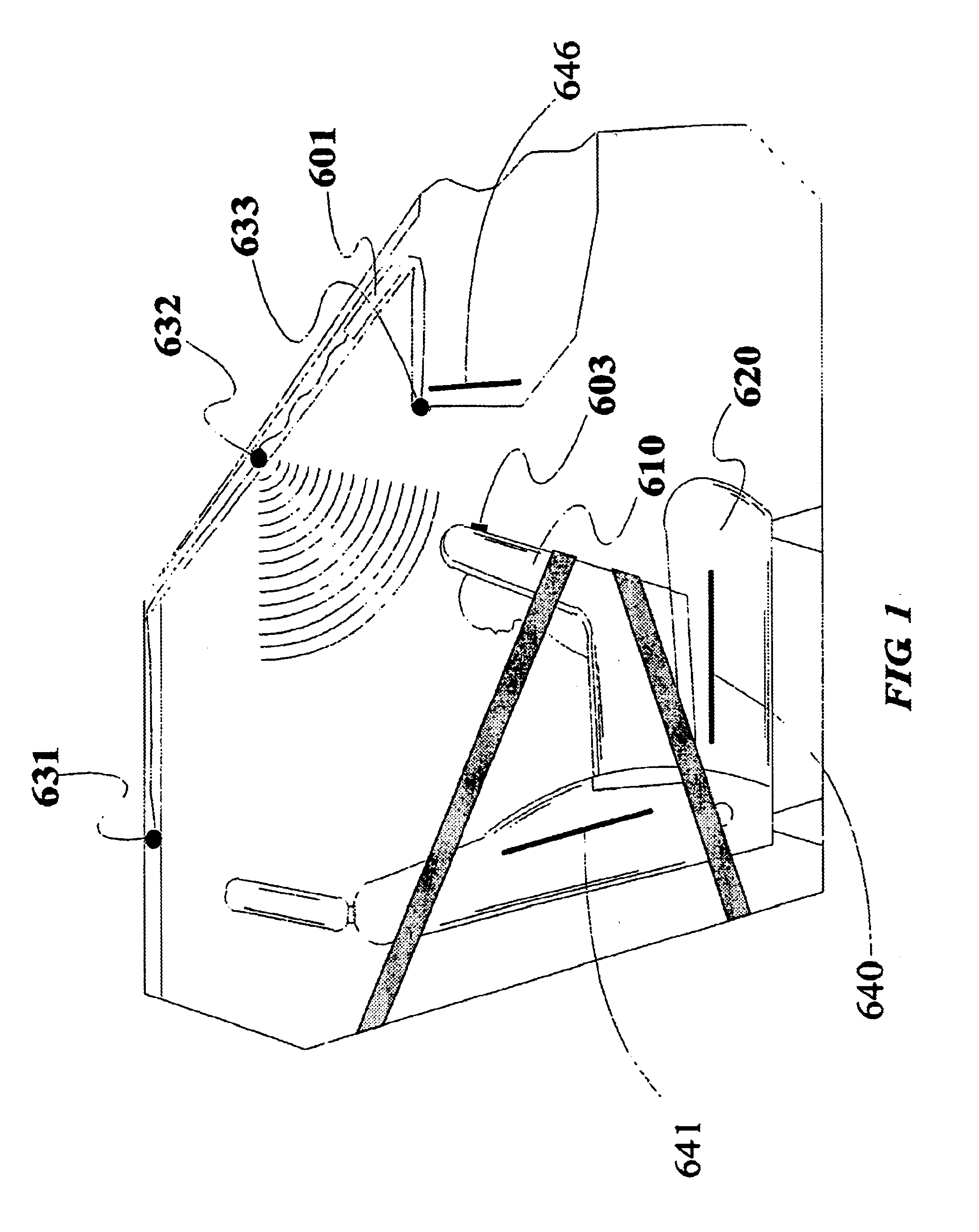
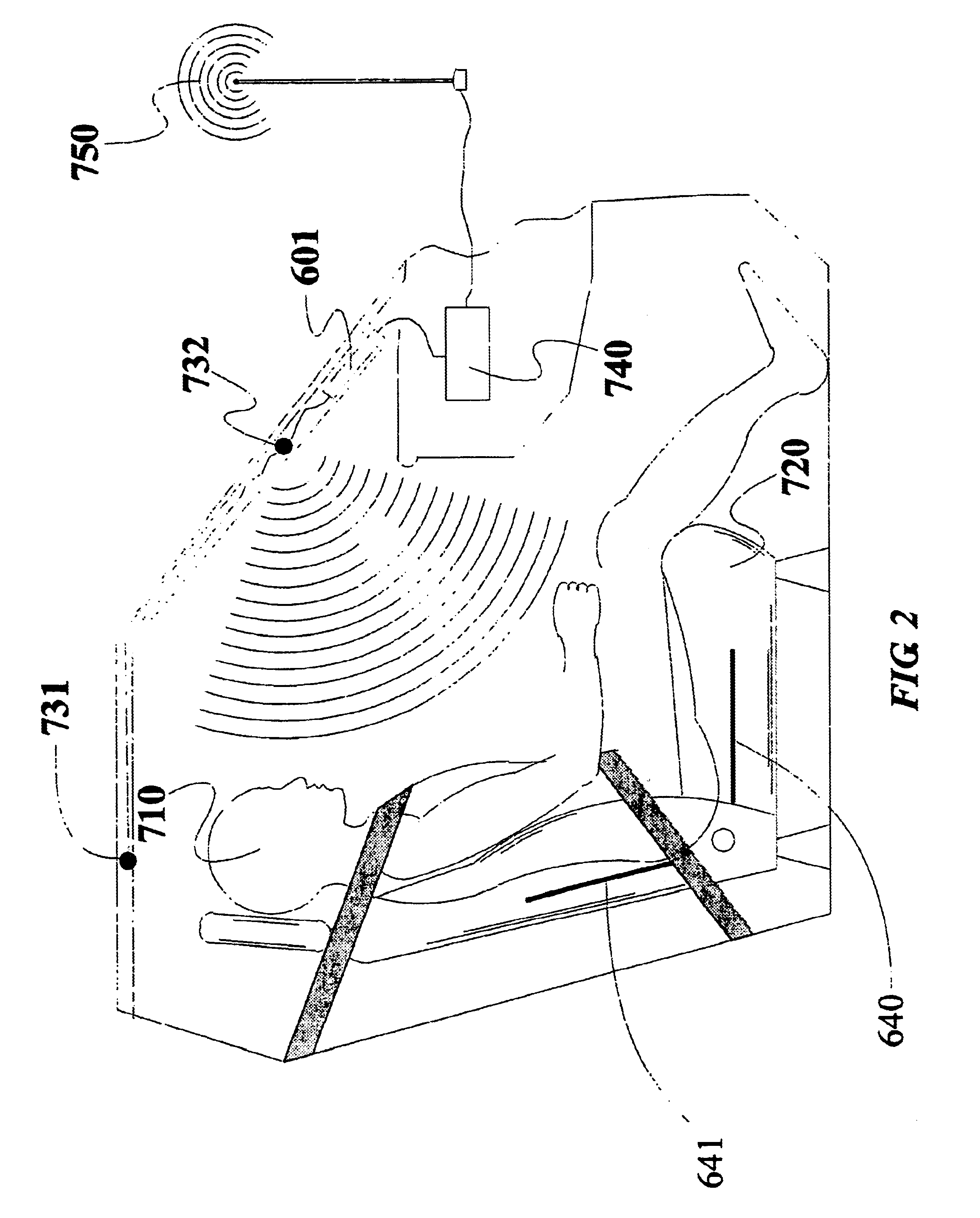
Referring to the accompanying drawings wherein the same reference numerals refer to the same or similar elements, FIG. 1 is a side view, with parts cutaway and removed of a vehicle showing the passenger compartment containing a rear facing child seat 610 on a front passenger seat 620 and one mounting location for a vehicle interior monitoring system in accordance with the invention. The interior monitoring system is capable of detecting the presence of an object, determining the type of object, determining the location of the object, and / or determining another property or characteristic of the object. A property of the object could be the orientation of a child seat, the velocity of an adult and the like. For example, the vehicle interior monitoring system can determine that an object is present on the seat, that the object is a child seat and that the child seat is rear-facing. The vehicle interior monitoring system could also determine that the object is an adult, that he is drunk...

second embodiment

a valve cap 10′ in accordance with the invention is shown in FIG. 13B and comprises a SAW strain sensing device 15 that is mounted onto a flexible membrane 13 attached to the body 9′ of the valve cap 10′ and in a position in which it is exposed to the air in the chamber 12′. When the pressure changes in chamber 12′, the deflection of the membrane 13 changes thereby changing the stress in the SAW device 15.

Strain sensor 15 is thus a differential pressure-measuring device. It functions based on the principle that changes in the flexure of the membrane 13 can be correlated to changes in pressure in the chamber 12′ and thus, if an initial pressure and flexure are known, the change in pressure can be determined from the change in flexure.

FIGS. 13A and 13B therefore illustrate two different methods of using a SAW sensor in a valve cap for monitoring the pressure inside a tire. The precise manner in which the SAW sensors 11,15 operate is discussed fully below but briefly, each sensor 11,15...


PUM


Abstract

Control system and method for controlling an occupant restraint system in which a plurality of electronic sensors are mounted at different locations on the vehicle, each sensor providing a measurement related to a state thereof or a measurement related to a state of the mounting location. A processor is coupled to the sensors and diagnoses the state of the vehicle based on the measurements of the sensors. The processor controls the occupant restraint system based at least in part on the diagnosed state of the vehicle in an attempt to minimize injury to an occupant.

Description

FIELD OF THE INVENTIONThe present invention relates to methods and apparatus for controlling an occupant restraint system in a vehicle based in part on the diagnosed state of the vehicle in an attempt to minimize injury to an occupant.BACKGROUND OF THE INVENTIONIt is now generally recognized that it is important to monitor the occupancy of a passenger compartment of a vehicle. For example, U.S. Pat. No. 5,829,782 (Breed et al.) describes a vehicle interior monitoring system that utilizes pattern recognition techniques and wave-receiving sensors to obtain information about the occupancy of the passenger compartment and uses this information to affect the operation of one or more systems in the vehicle, including an occupant restraint device, an entertainment system, a heating and air-conditioning system, a vehicle communication system, a distress notification system, a light filtering system and a security system.Of particular interest, Breed et al. mentions that the presence of a ch...

Claims


Application Information

Patent Timeline
Patent Type & Authority Patents(United States)
IPC IPC(8): B60N2/26B60N2/02B60C19/00B60N2/28B60C11/24B60C23/06B60C23/04B60C23/02G07C5/00G07C5/08B60R21/00B60R21/16B60R21/20B60R21/213B60R21/231B60R21/233B60R21/235B60R21/30G02B27/00G02B27/01G06V10/143G06V30/194
CPCB60C11/24G06K9/66B60C23/0449B60N2/0232B60N2/0276B60N2/2863B60R21/20B60R21/213B60R21/232B60R21/233B60R21/235B60R21/30G02B27/01G06K7/10178G07C5/008G07C5/0808B60C11/246G06K9/2018G06K9/6269G06K9/00838G06K9/00832B60C19/00B60R2021/0004B60R2021/23107B60R2021/23153B60R2021/23161B60R2021/23169B60R2021/23519B60R2021/23523B60R2021/23557B60R2021/2358B60R2021/2359G02B2027/014G02B2027/0187B60N2002/0272G06V20/593G06V20/59G06V10/143G06V30/194G06F18/2411B60N2/0272B60N2/02246
Inventor BREED, DAVID S.
Owner AUTOMOTIVE TECH INT
Why Eureka
Try Eureka