Method and device for near-field measuring of non-controlled radiation

a technology of non-controlled radiation and near-field measurement, which is applied in the direction of resistance/reactance/impedence, instruments, transmission monitoring, etc., can solve the problems of difficult measurement, impossible to provide, and extremely difficult to measure these different signals

Inactive Publication Date: 2005-02-01
CHARTOLEAUX
View PDF7 Cites 37 Cited by
  • Summary
  • Abstract
  • Description
  • Claims
  • Application Information

AI Technical Summary

Benefits of technology

The device shown in FIGS. 1 and 2 is an original spherical positioner making it possible to collect all the data necessary for implementing the measuring method according to the invention, and for processing the associated data. It is especially adapted for carrying out measurements on mobile phone equipment at 900 or 1800 MHz.

Problems solved by technology

The measurements of these different signals are extremely difficult to implement by using present measurement techniques.
As shown below, these measurements are even more difficult since the supply to the equipment concerned is not controlled.
The measurement protocol recommended by the CISPR has serious disadvantages:at low frequency, the hypotheses of distant field used are a source of errors;the measurement antenna is in the Fresnel zone (near field) of the AUT and the structure of the radiated waves is not a plane wave structure contrary to the approximation applied;coupling phenomena difficult to take into account, and capable of affecting the validity of the measurement, may occur between the AUT and the measurement antenna, or between the antenna and its ground image, and bring about a modification of the value of the antenna factor.because of the angular truncation above and the influence of the ground, the method does not make it possible to provide a precise diagram of the AUT radiation, nor to describe the emitted signals.finally, these measurements are specified on normalized measurement sites which can be located in open areas (Open Area Test Site) or semi-echo-free chambers.
These sites must be very large sized, are often costly and impractical, and are subject to many imperfections: spurious emissions, disturbing atmospheric phenomena, or furthermore poor performance of absorbents, shielding defects, etc.
However, it is clear that in this measurement configuration, the apparatus is not working under its normal utilization conditions, since its supply remains controlled.
The validity of this type of measurement is, thus, limited to the measurement conditions (see J. Hald et al.
It certainly remains possible to carry out measurements without being in control of the source, but then the correlation operation mentioned above cannot be carried out and the near field measurements are in amplitude only.
These measurements are difficult and expensive to implement.
However, according to the authors, this method has not been able to provide reliable limits for radiated electric field at every distance from the AUT.
But this hypothesis of simultaneous measurement at all points of the surface is not realistic because the complexity of the measuring apparatus needed would rule it out.
Nonetheless this method of measurement is still not completely mastered and strict precautions have to be taken during the measurement of highly dispersive systems.
Furthermore, present measurements do not make it possible to provide a radiation diagram associated with a useful signal, nor to know the total radiated power associated with this signal.
In this sense, hardening measurements carried out at present by prior art methods remain very incomplete.

Method used


Image

  • Method and device for near-field measuring of non-controlled radiation
  • Method and device for near-field measuring of non-controlled radiation
  • Method and device for near-field measuring of non-controlled radiation

Examples


Embodiment Construction

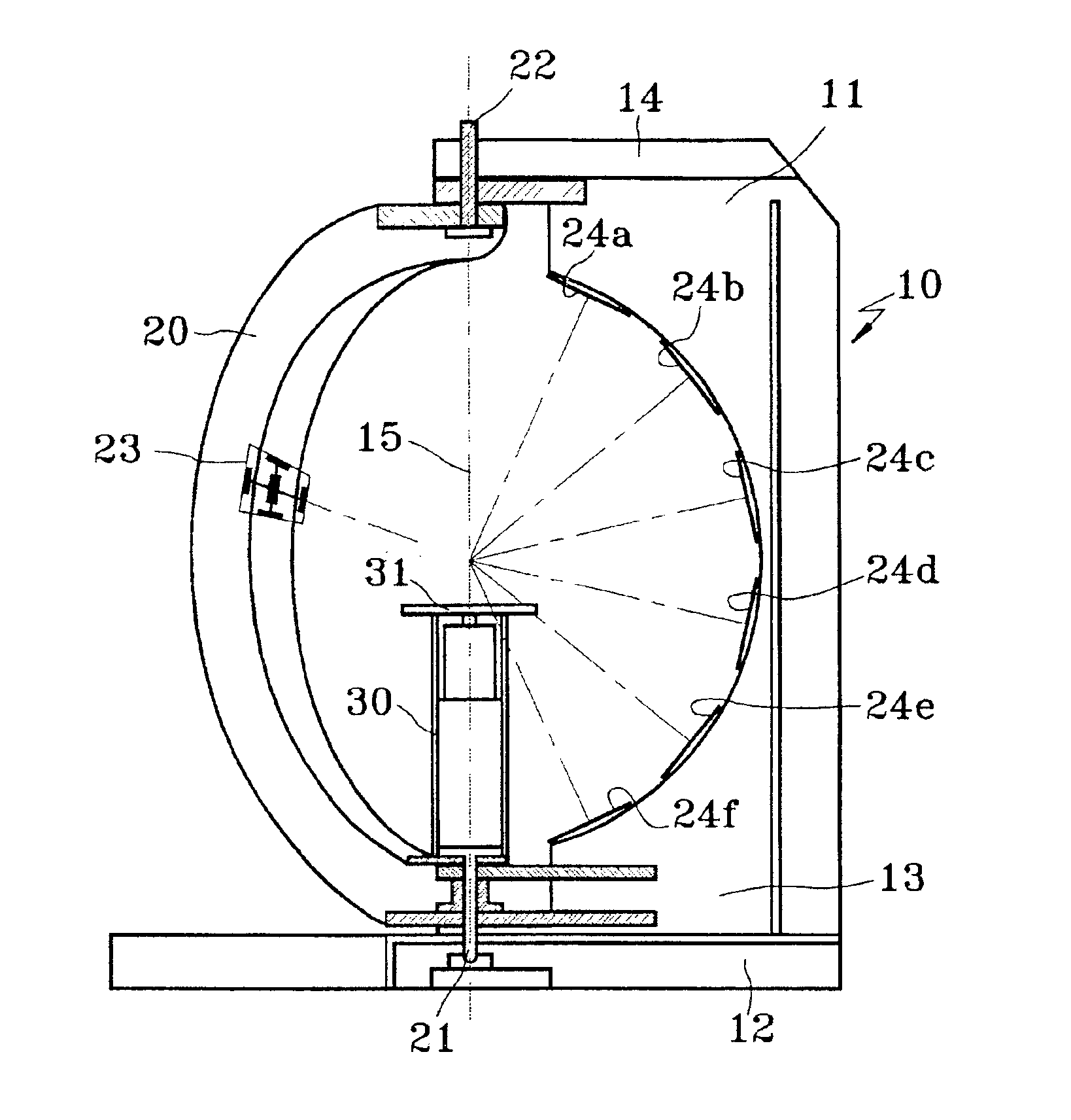
The device is constituted of a fixed support frame 10 comprising an arch 11 mounted on a base 12. Between the lower 13 and upper 14 branches of the arch a second support frame 20 is installed which is mounted to pivot around pivots 21, 22. This pivoting support frame 20 forms a curved arm usually integral with a turning plate 30 adjustable in height and comprising a reception platform 31 for the apparatus to be analyzed (the AUT, not shown here). The arm 20 and the plate 30 can nonetheless be separated from each other by disengagement.

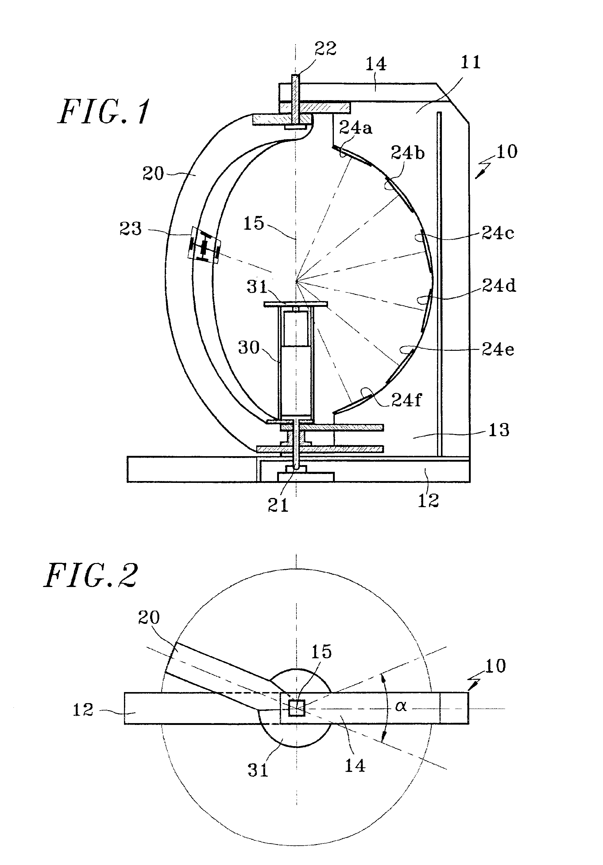
As can be seen in the view from above (FIG. 2), the mobile arm 20 is able to follow a course of practically 360° around the axis of rotation 15. However, in an angular zone next to the arch 11 of the fixed frame 10, the arm 20 comes up against the stop of the arch 11. At this moment, it is thus possible to allow the plate 30 to finish a complete turn, up to 360°, by disengaging it from the mobile arm 20.

The mobile arm 20 is equipped with a sensor 23, c...


PUM


Abstract

An electric field emitted by an electronic equipment is measured by producing at least one radiation measurement in the radiating field of the equipment. Several sets of simultaneous near-field measurements, within a measuring surface located at a short distance from the equipment, are performed. The sets of performed measurements are processed by estimating the statistical properties of the radiated field at any point outside the measuring surface.

Description

FIELD OF THE INVENTIONThe field of the invention involves systems for measuring the electric field emitted by any electronic equipment.BACKGROUND OF THE INVENTIONThe fields radiated from an electronic equipment, which will be named afterwards as “AUT” an abbreviation for “Apparatus Under Test”, can be separated into radiation that is intentional, sought and inherent to its operation, and into non-intentional radiation.Thus, a mobile phone transmits an expected radiation, required for communication, as well as complementary spurious emissions, which are non-intentional. A table-top computer, and in particular its screen, usually emits non-intentional radiation.Non-intentional radiation can be divided between useful emissions, that is to say carriers of significant information, and non-useful emissions (noise).At a time when telecommunications systems are enjoying extraordinary expansion, better understanding of emitted radiation is primordial since it is essential to guarantee a cert...

Claims


Application Information

Patent Timeline
Patent Type & Authority Patents(United States)
IPC IPC(8): G01R29/08H04B17/00
CPCG01R29/0814H04B17/309G01R29/0892
Inventor FOURESTIE, BENOITALTMAN, ZWIWIART, JOEGRANDSIMON, GERARDBOLOMEY, JEAN-CHARLES
Owner CHARTOLEAUX
Why Eureka
Try Eureka