Method of fabricating a clipless bicycle pedal

a bicycle pedal and manufacturing method technology, applied in the field of four-sided clipless bicycle pedals, can solve the problems of high manufacturing cost of four-sided pedals, inability to meet the needs of bicycle users, so as to achieve a large market, reduce the overall cost of the pedal, and make the pedal far more economically.

Inactive Publication Date: 2005-02-08
CRANK BROS INC
View PDF3 Cites 11 Cited by
  • Summary
  • Abstract
  • Description
  • Claims
  • Application Information

AI Technical Summary

Benefits of technology

An object of the present invention is to provide an inexpensive clipless mechanism of a four-sided clipless pedal for bicycles.
Another object of the present invention is to provide an inexpensive method for making the clipless mechanism of a four-sided clipless pedal for bicycles, which can be made in high quantities with a short lead time.
Another object of the present invention is to provide an inexpensive method for making the clipless mechanism of a four-sided clipless pedal for bicycles, which can work with multiple configurations of the four-sided clipless pedal including plain and platform versions. In this way, tooling and inventory can be minimized and simplified.
Yet another object of the present invention is to provide an inexpensive method for making the clipless mechanism of a four-sided clipless pedal for bicycles, which pedal retains the riding performance advantages of more expensive four-sided clipless pedals that are already commercially available. Specifically, the four-sided clipless pedal must still be able to engage the cleat, be sturdy enough to meet the rigorous demands of mountain biking and yet be easy to use. It should be easy to engage and disengage and be resistant to effects of dirt or debris which might otherwise damage or incapacitate a locking mechanism. It should be small enough to be substantially retained within the recessed area in the soles of commercially-available mountain bicycle shoes so that it is generally protected from impact and does not interfere with walking. It should minimize the distance from bottom of the cycling shoe to the centerline of the pedal to lower the rider's center of gravity and make pedaling more stable, minimize the distance from the centerline of the pedal to the bottom of the pedal for improved ground clearance while pedaling. It should also have easy maintenance including easy disassembly and reassembly, be relatively light in weight and be highly resistant to clogging with mud.
Stamping in general, and progressive stamping in particular, is an extremely fast and inexpensive process. The clipping mechanism parts as described herein can be easily progressively stamped at a rate of 4 per second (14,400 per hour) using one progressive stamping tool. By using an automated welding fixture, it is also easy and fast to reliably weld the parts. For a four-sided pedal version without an external platform, there are also two simple screw machined parts that are welded to one of the two clipping components. For four-sided pedal versions with a platform style, the parts do not require this additional step.
By using the above method of manufacture, the profile of the pedal can remain the same as pedals made using more expensive manufacturing methods. This means that the same cleat that works with the more expensive pedals will work with the less expensive pedals. The above method of manufacturing the clipping mechanism allows the four-sided pedal to be made far more economically than other manufacturing methods and dramatically reduces the overall cost of the pedal. This allows the pedal to sell in a far larger market. Also, by using the above method of manufacture, the same stamped components can be used for different models of four-sided pedals such as those with and without platforms. The inventive features hereof although intended primarily for use in bicycle pedals, are also applicable to other cleat receiving apparatus such as snow board bindings and the like.

Problems solved by technology

The disadvantage is that double side entry pedals are generally more complex and heavier than single side entry pedals.
The disadvantage of the four-sided pedal is a relatively high manufacturing cost.
However, the success will always be limited by the cost.
The technology of the four-sided pedals is extremely good and well proven in the market, but the cost of manufacture is simply too high for selling to the largest segment of the market.
The problem with using bent wire / machining / welding processes for the clipping mechanism is that the machined parts are somewhat complex and it is difficult to accurately align all the parts during the welding process.
Forging the clipping mechanism would be very expensive because there are still a great number of steps in the process and the flash is difficult to trim.
It is especially difficult to trim the flash because the parts must remain straight or else they will not function properly and it takes a large force for trimming.
Machining the clipping mechanism as described in the '885 patent is also expensive because of the protrusions and because there is multi-axis machining required.
Also, the spring shown in the preferred embodiment of the '885 patent is difficult to make, because the wire is bent back over itself.
Investment casting works extremely well functionally for making these parts, but is so labor intensive that it is expensive.
Also, it is difficult to investment cast these parts straight because the clipping bars are relatively thin and especially fragile when still in their wax state.
These four components can easily cost more than the rest of the pedal components combined.
Another problem with investment casting the clipping mechanism of the pedal is that because there are so many steps to the process, the lead time for making parts is long.
This can cause delivery problems if demand exceeds expectations.
Also, capacity can be a problem because most casting companies have a relatively low daily output.
As discussed above, investment casting is expensive because it involves so many labor intensive steps.
If the metal used is hardenable such as the 17-4ph stainless steel used for most of the marketed pedals currently made under the '885 patent, then each part should be annealed, or else they are too hard to easily cut or machine.
It is no surprise that investment casting is so expensive.
Unfortunately, die casting can normally only be used to cast weaker metals such as zinc, aluminum and magnesium.
These metals can't be reasonably used for the bars primarily because there is a size limitation.
Also, die cast metals such as zinc, aluminum and magnesium are so soft that they would wear more quickly, especially where the cleat rubs against the clipping mechanism.
Unfortunately, MIM, while less labor intensive than investment casting, requires expensive tooling, expensive material preparation, expensive equipment, and several steps.
Therefore, it would still be a relatively expensive process to use for making the clipless mechanism.

Method used


Image

  • Method of fabricating a clipless bicycle pedal
  • Method of fabricating a clipless bicycle pedal
  • Method of fabricating a clipless bicycle pedal

Examples


Embodiment Construction

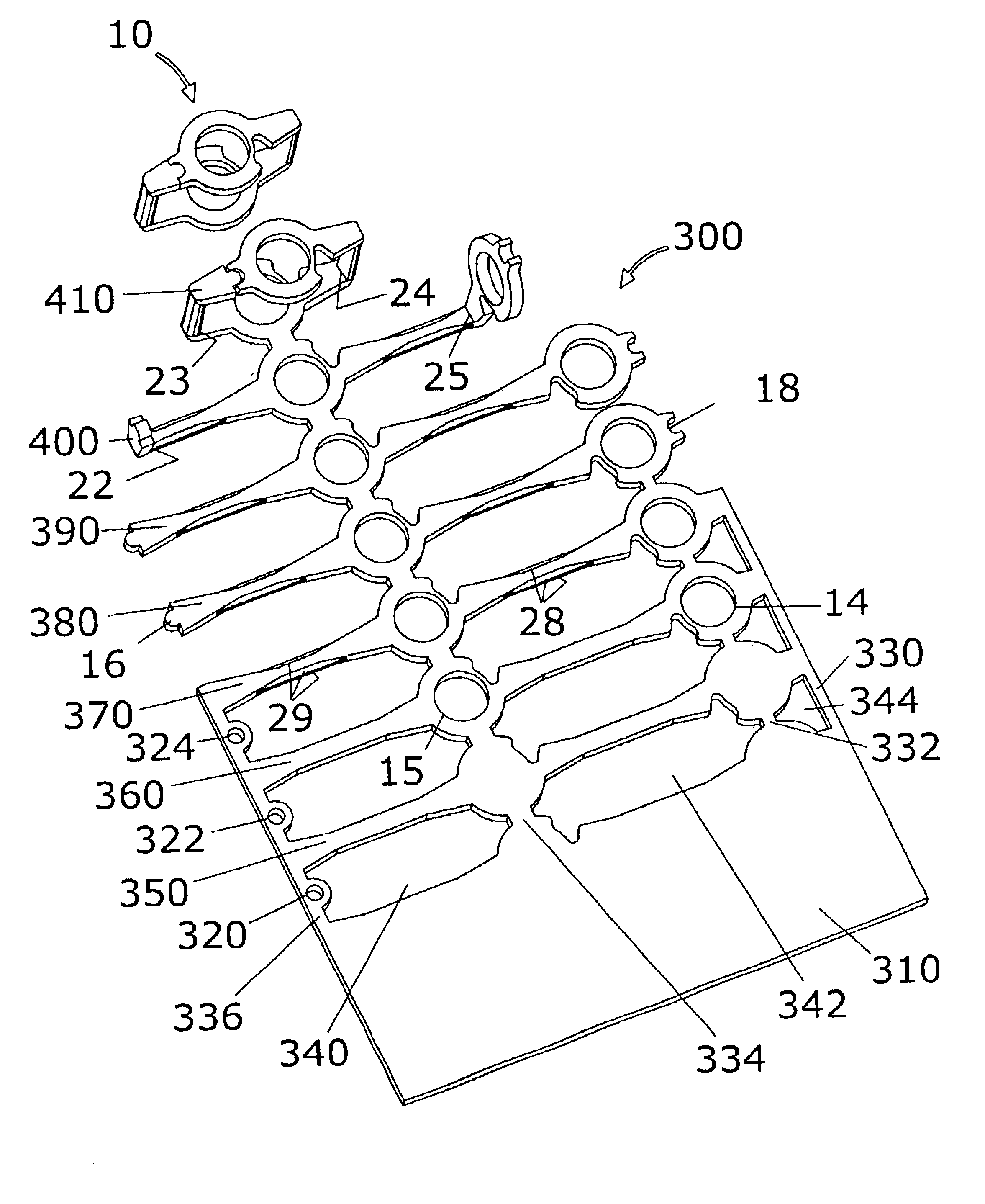
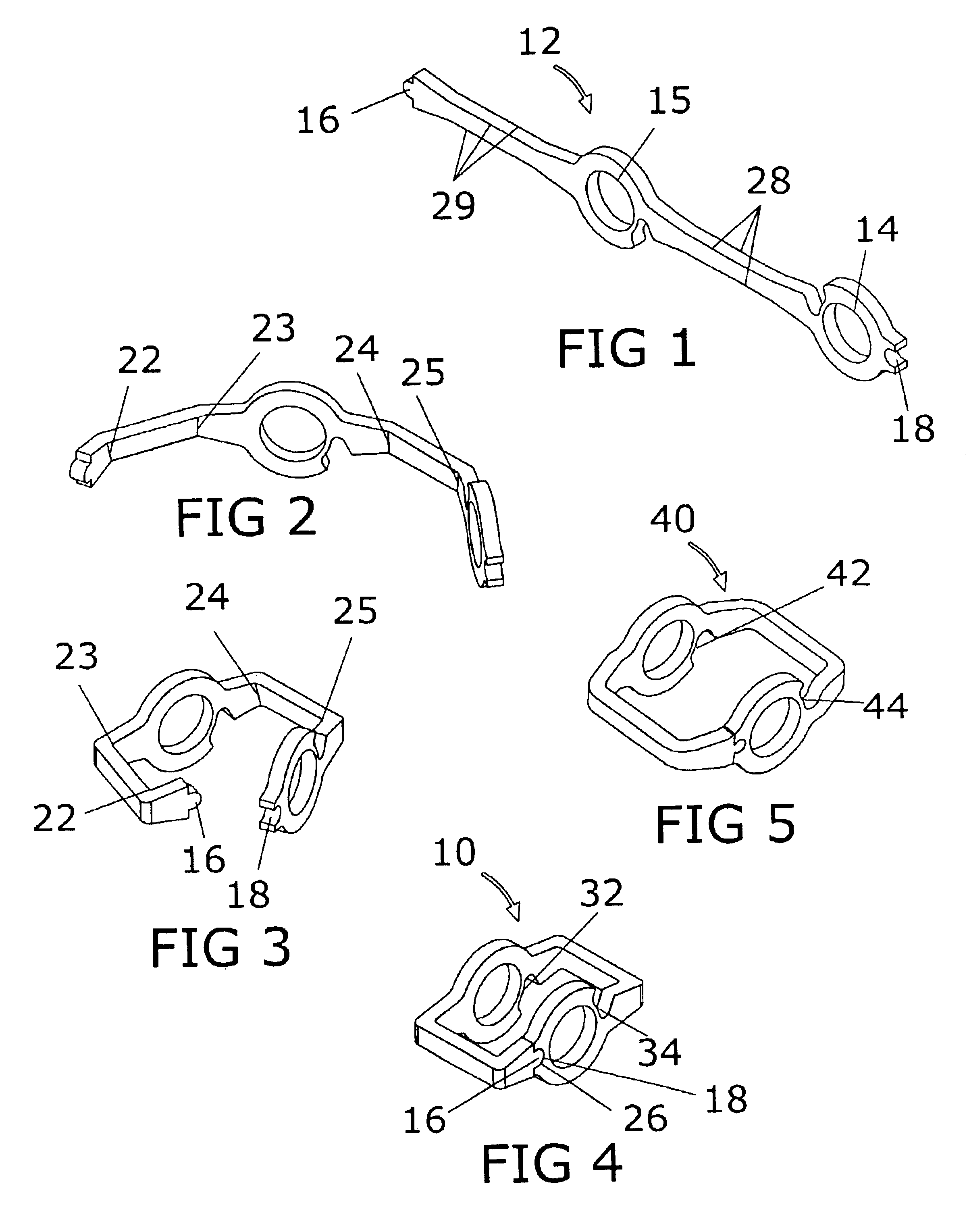
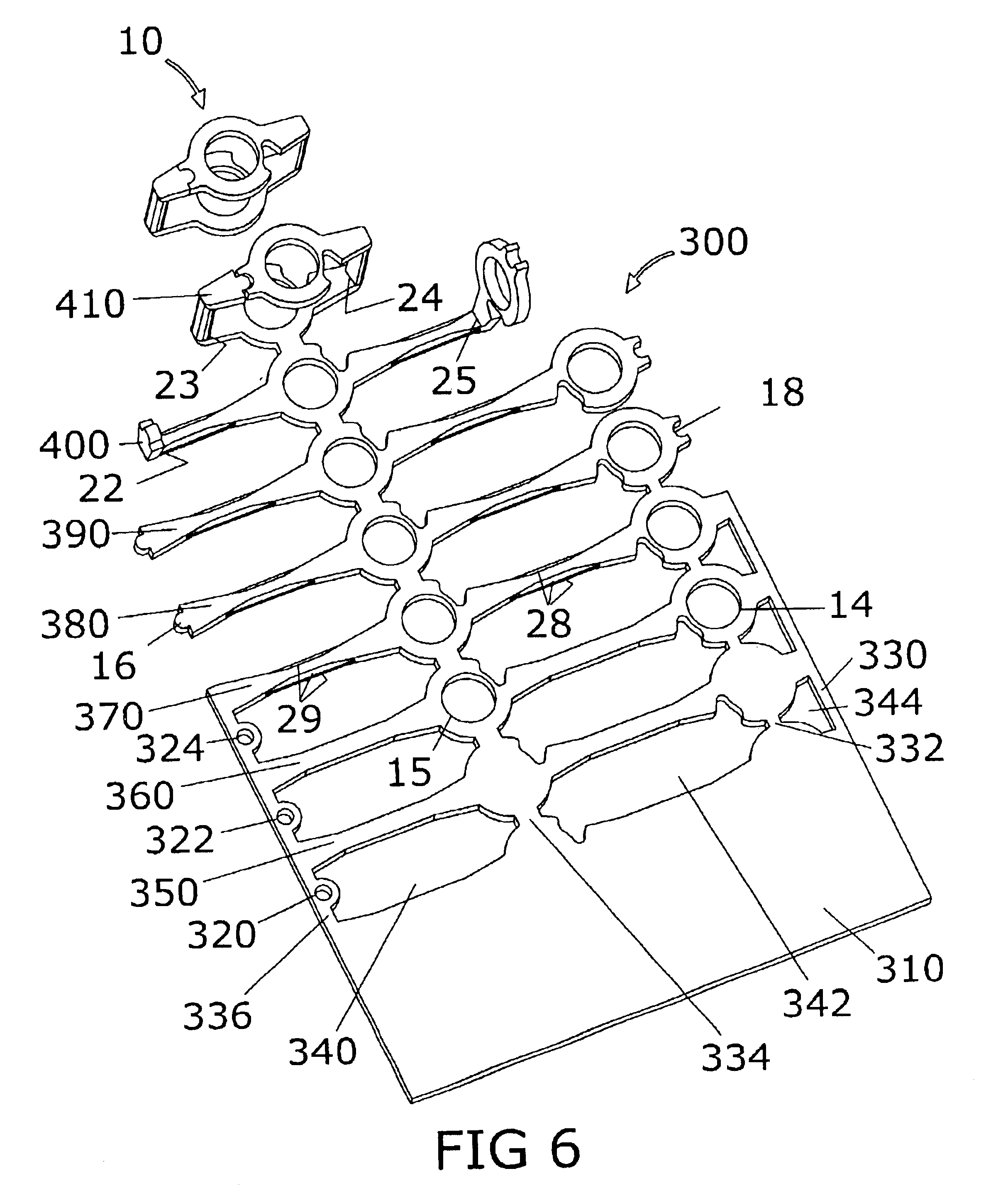
The preferred embodiment of the present invention may be understood by referring to FIGS. 1-20. It will be seen that a low cost four-sided clipless pedal mechanism is comprised primarily of two stamped and welded components: an inner wing 10 and outer wing 40. Inner wing 10 and outer wing 40 are preferably stamped using a progressive stamping method in order to obtain their three dimensional shapes and then welded closed. FIGS. 1-4 show a conceptual stamping method as a four step process, but the number of stamping stations could vary greatly depending on the actual design of the stamping tool and the thickness and properties of the material chosen. For example, the process could actually be done with ten steps instead of four. In a specific example, a progressive stamping stages plate 300 is shown to form an inner wing 10 in seven stages 350, 360, 370, 380, 390, 400, and 410. Progressive stamping is an extremely cost effective method of stamping inner wing 10 and outer wing 40. A s...


PUM

PropertyMeasurementUnit
timeaaaaaaaaaa
surface areaaaaaaaaaaa
weightaaaaaaaaaa

Abstract

A clipless mechanism for a four-sided clipless bicycle pedal is made by a stamping and welding process. The stamping is preferably a progressive stamping process. The stamped parts include two components, an inner wing and an outer wing. The two stamped components are generally similar in shape to each other, but the inner wing fits within the outer wing. Each part is first stamped as a flat pattern by a progressive die. Each part then has radii stamped into the edges by the second station of the progressive die. Next, each part is partially folded by the third station of the progressive die. Then each part is folded completely by the fourth station of the progressive die. The actual number of steps may vary depending upon the material chosen, the thickness of the material and the design of the stamping tool. Then each part is welded closed and the resulting rectangular wings are assemblied in juxtaposed orthogonal relation to provide four shoe cleat engaging receptacles.

Description

BACKGROUND OF THE INVENTION1. Field of the InventionThis invention relates generally to four-sided clipless bicycle pedals and more particularly to a method of manufacturing such pedals.2. Background ArtOriginally, pedals were simply platforms to push down on. Then came pedals with toe clips, which were essentially cages on top of the pedals that the rider's shoes fit into. Then came “clipless” pedals, which securely held rider's shoes to the pedals without the toe clip (hence “clipless”).A number of clipless pedal designs have been made commercially available. A clipless pedal is a pedal that clamps to the rider's shoe via a cleat mounted to the bottom of the rider's shoe. Typically, to unclip the rider twists his foot outwards. The first clipless pedals were single side entry because they had latch and release mechanisms on only one side of the pedal. The next clipless pedals were double side entry because they had latch and release mechanisms on opposite sides of the pedal. The a...

Claims


Application Information

Patent Timeline
Patent Type & Authority Patents(United States)
IPC IPC(8): B62M3/08B62M3/00
CPCB62M3/086Y10T74/2168Y10T29/49622
Inventor HERMANSEN, FRANKWINEFORDNER, CARL
Owner CRANK BROS INC
Why Eureka
Try Eureka