Reciprocating saw

a saw and reciprocating technology, applied in the field of reciprocating saws, can solve the problems of increased manufacturing cost of the saw, tight tolerance of the joint, and required machining, so as to reduce the cost of manufacturing the saw, reduce the noise level of the saw, and prolong the life of the saw

Inactive Publication Date: 2005-02-08
MILWAUKEE ELECTRIC TOOL CORP
View PDF60 Cites 38 Cited by
  • Summary
  • Abstract
  • Description
  • Claims
  • Application Information

AI Technical Summary

Benefits of technology

One independent advantage of the present invention is that, because a wear compensating socket is provided in the spindle, the tolerance of the joint between the drive arm of the wobble plate and the spindle bore does not have to be as tightly machined. This reduces the cost of manufacturing the saw. Additionally, the wear compensating socket adjusts for wear between the drive arm and the spindle bore extending the life of the saw and reducing the noise level of the saw.
Another independent advantage of the present invention is that because the cam member is separate from the drive shaft, the cam member can be easily replaced or interchanged. This provides easy replacement of a worn cam member or interchangeability with different cam members to change the pattern of the orbital blade movement to affect the cutting performance of the reciprocating saw.
Yet another independent advantage of the present invention is that because the orbital actuation assembly is positioned at the top and center of the tool, the actuation assembly is operable with either hand. Further, the orbital actuation assembly maintains its center at the spindle axis allowing the orbital actuation lever to seal the opening through which the lever extends from the housing. In addition, because the orbital adjustment member or lock-out plate lifts the cam

Problems solved by technology

The reciprocating saws described above have several independent problems.
The required machining increases the cost of manufacturing the saw.
Also, as the joint between the wobble plate drive arm and the spindle bore wears, the tight tolerance of the joint is lost so that wear of the saw increases.
The loose joint between the drive arm and the spindle bore also causes increased noise.
One independent problem with a reciprocating saw having an orbital drive system in which cam member is fixed to the drive shaft is that the cam member is not replaceable or interchangeable without changing the attached drive shaft and/or drive gear.
Th

Method used


Image

  • Reciprocating saw
  • Reciprocating saw
  • Reciprocating saw

Examples


Embodiment Construction

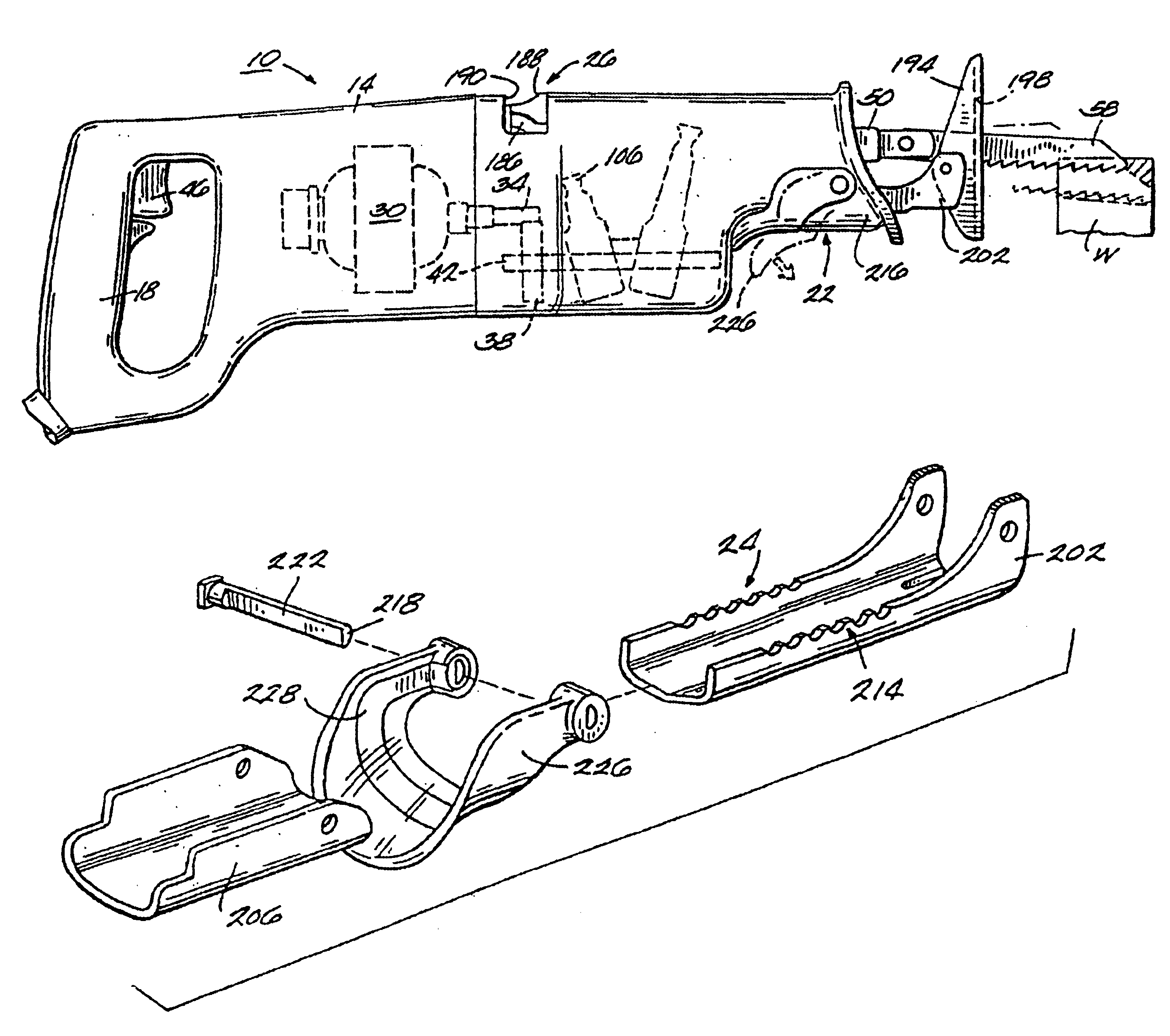
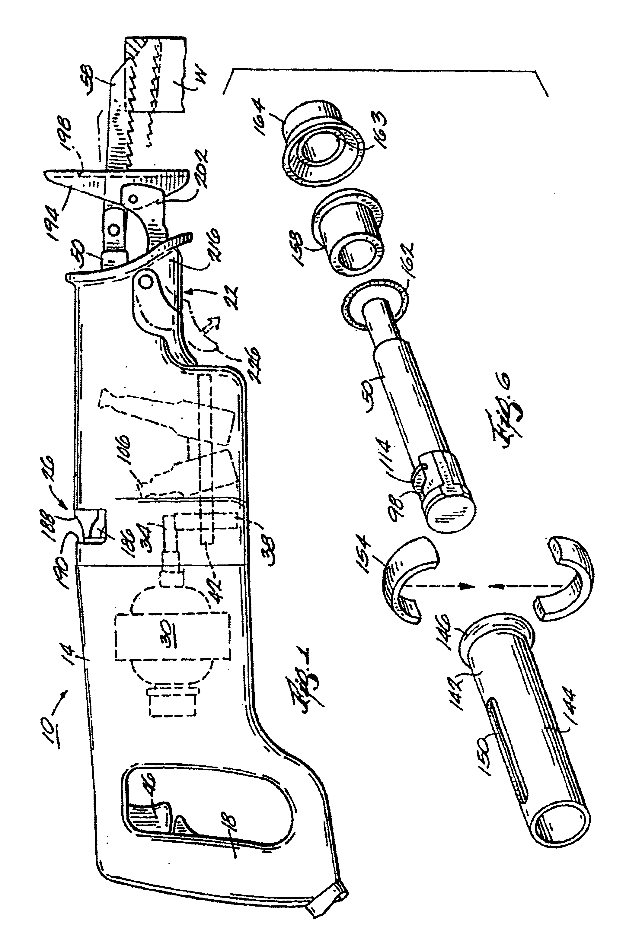
A reciprocating saw 10 embodying the present invention is illustrated in FIG. 1. The reciprocating saw 10 generally includes a main housing 14 having an operator's handle 18, a forward portion 22 opposite the handle 18, and an upper portion 26.

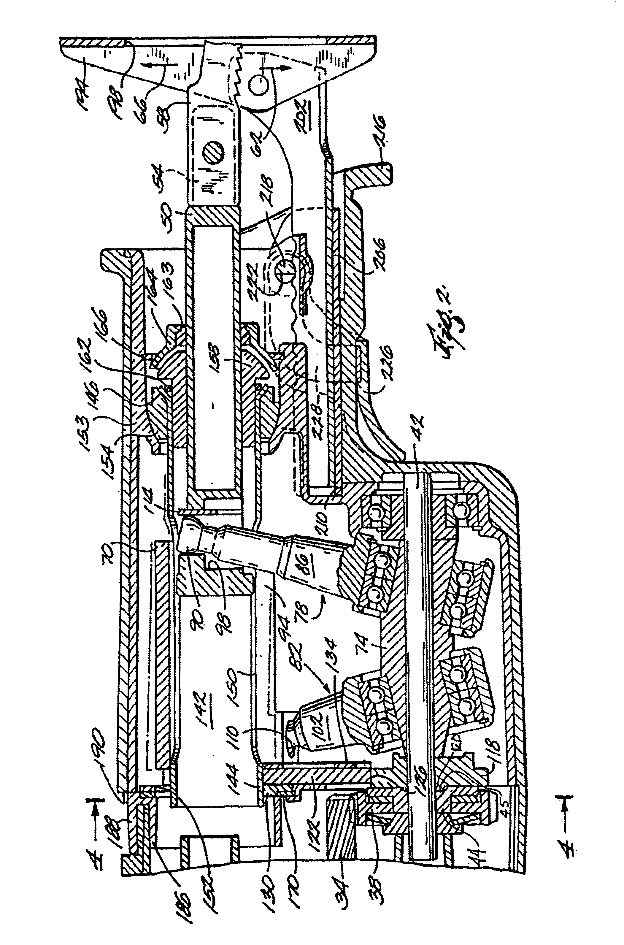
An electric motor 30 is supported by the housing 14. The motor 30 includes a drive pinion 34 that engages a gear 38 mounted on a drive shaft 42. The drive shaft 42 is rotatably mounted within the housing 14. A drive hub 44 is mounted on the drive shaft 42 and is connected to the gear 38. The hub 44 defines an off-center pocket 45. A switch 46 is located in the operator's handle 18 for energizing the motor 30 to rotate the drive shaft 42.

A spindle 50 (partially shown) is supported by the housing for reciprocating and pivoting movement (e.g., orbital movement) relative to the housing 14. As shown in FIG. 2, the spindle 50 includes a front end 54 that supports a saw blade 58, which is designed to cut in a cutting direction 62 (i.e., in the direct...


PUM


Abstract

An reciprocating saw comprising a housing, a motor, a spindle movably supported within said housing and having a front end adapted to support a saw blade, a drive assembly, and an adjustable shoe assembly. The adjustable shoe assembly includes a shoe, a shoe support member pivotally supporting the shoe, a locking member pivotally supported by the housing, and a lever connected to the locking member.

Description

BACKGROUND OF THE INVENTIONThe present invention generally relates to reciprocating saws.Reciprocating saws are used to cut a variety of objects made from a variety of materials, such as metal pipes, wood and dry wall. Such saws generally include a housing and a spindle mounted in the housing for reciprocating motion along an axis that is parallel to the longitudinal extent of the spindle. An electric motor provides power to the spindle through a mechanical reciprocating device that converts the rotary motion of a motor shaft to reciprocating motion. Such mechanical reciprocating devices can, for example, include an eccentric drive, as disclosed in U.S. Pat. No. 5,079,844, or a wobble plate drive, as disclosed in U.S. Pat. Nos. 5,025,562 and 5,050,307. In a typical wobble plate drive, the drive arm of a primary wobble plate has a spherical tip that engages a suitable bore defined in the reciprocating spindle. The drive can also include a secondary wobble plate having a drive arm wit...

Claims


Application Information

Patent Timeline
IPC IPC(8): B23D49/00B23D51/00B23D51/16B23D49/16B27B19/04B27B19/09
CPCB23D51/16B23D49/165
Inventor BEDNAR, THOMAS RICHARDNEITZELL, ROGER DEANSTEELE, MICHAEL SCOTT
Owner MILWAUKEE ELECTRIC TOOL CORP
Why Eureka
Try Eureka