Variable rate meter drive system

a variable rate, drive system technology, applied in the direction of servomotors, potato planters, furrow making/covering, etc., can solve the problems of inability to change the meter rate during field operation, cost, complexity, wear, etc., and achieve the effect of eliminating the drive creep of the metering mechanism and being manufactured inexpensively

Inactive Publication Date: 2005-02-08
CNH IND CANADA
View PDF10 Cites 42 Cited by
  • Summary
  • Abstract
  • Description
  • Claims
  • Application Information

AI Technical Summary

Benefits of technology

It is another advantage of this invention that the variable rate drive system can be operated to vary the rate at which product is dispensed to the ground while the air seeder is moving in operation across the field.
It is still another feature of this invention that the drive system efficiently uses hydraulic resources (low flow and low pressure).
It is still another advantage of this invention that the variable rate drive system can be manufactured inexpensively.
It is yet another feature of this invention that drive creep for the metering mechanisms is eliminated when the system is fully powered and the air seeder is stationary.

Problems solved by technology

For many mechanical systems, it is difficult to change the meter rate and for the majority of these systems, it cannot be changed during field operation.
Cost, complexity, and wear are other disadvantages of this conventional drive system.
Although this is a vast improvement over most conventional drive systems, the operator still has to manually drive the meters to calibrate the system and priming a stationary air system to reduce the lag time from the meter to the opener in field operation is not achievable.
Some manufactures have added hydraulic motors in the mechanical circuit to improve calibration functionality with additional cost and complexity to the overall system.
Pure electric meter drive systems have been developed but are not widely used because of the power demands and costs required to deliver electrical power to an aircart.
These systems are often attractive with one or two meter drives, but become unrealistic when three or more drives are required.
Although electrohydraulic drive systems successfully provide the functionality for calibration and priming without a ground speed input, the system is more costly than other systems.
The load on the fan motor sets the hydraulic pressure available to the meter drive circuit; therefore, when the fan load is reduced or the meter drive motor's pressure increases above the fan requirement the meter performance fails.
If the flow divider was not used, when the second load is shut off, oil would flow to the second circuit (lowest circuit pressure), starving the first operating circuit.
If the parallel load drops below the requirement for the meters problems develop with the drive system.
However, these systems require constant adjustment to maintain accurate meter rates due to the changing volumetric efficiency of the pumps and motors as oil temperature changes.
A ground drive system does not address priming or calibration of the meter and will not produce a hydraulic flow when the air seeder is stationary.
These systems are also often very cost prohibitive.
This system was designed for the power beyond port on the tractor auxiliary remotes, which is not readily available on older tractors.
This system in not cost-effective for an aircart.
This system is an enhancement to mechanical systems; however, this system could not be electrically primed, or calibrated as the input to the gearbox was driven from the wheels of the aircart.
The pump could not be used to calibrate or prime the system when stationary because it is tied to ground speed.
This system is very costly due to the additional pump, associated components and the structures required to draw power from the ground wheel.

Method used


Image

  • Variable rate meter drive system
  • Variable rate meter drive system
  • Variable rate meter drive system

Examples


Embodiment Construction

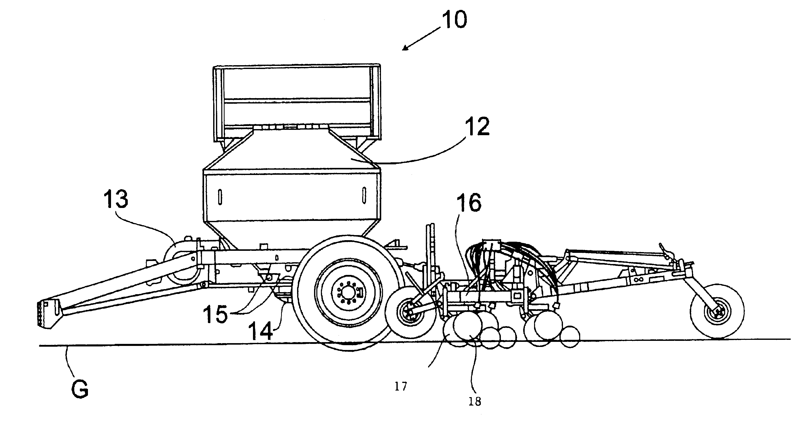
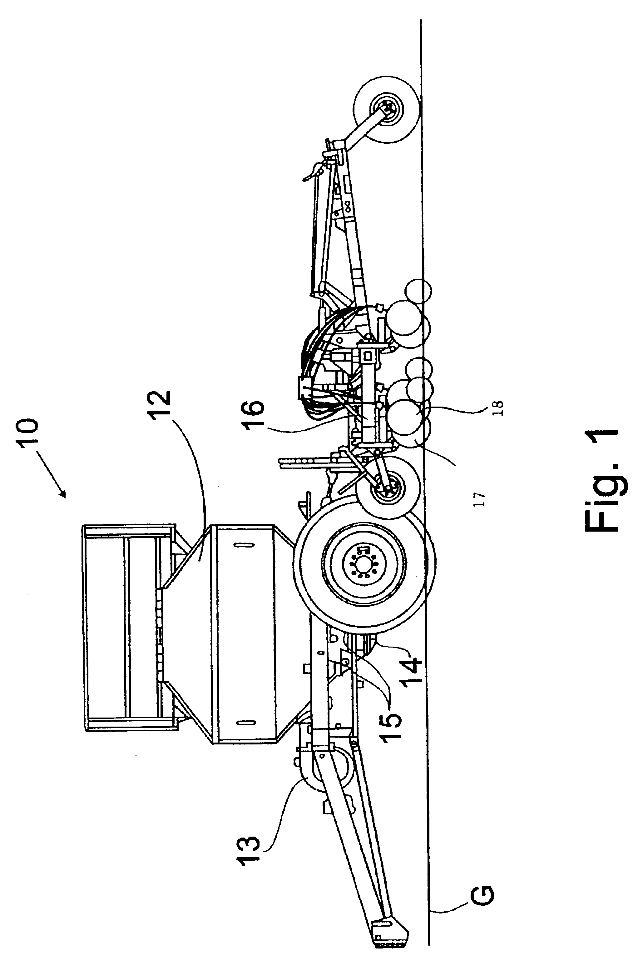
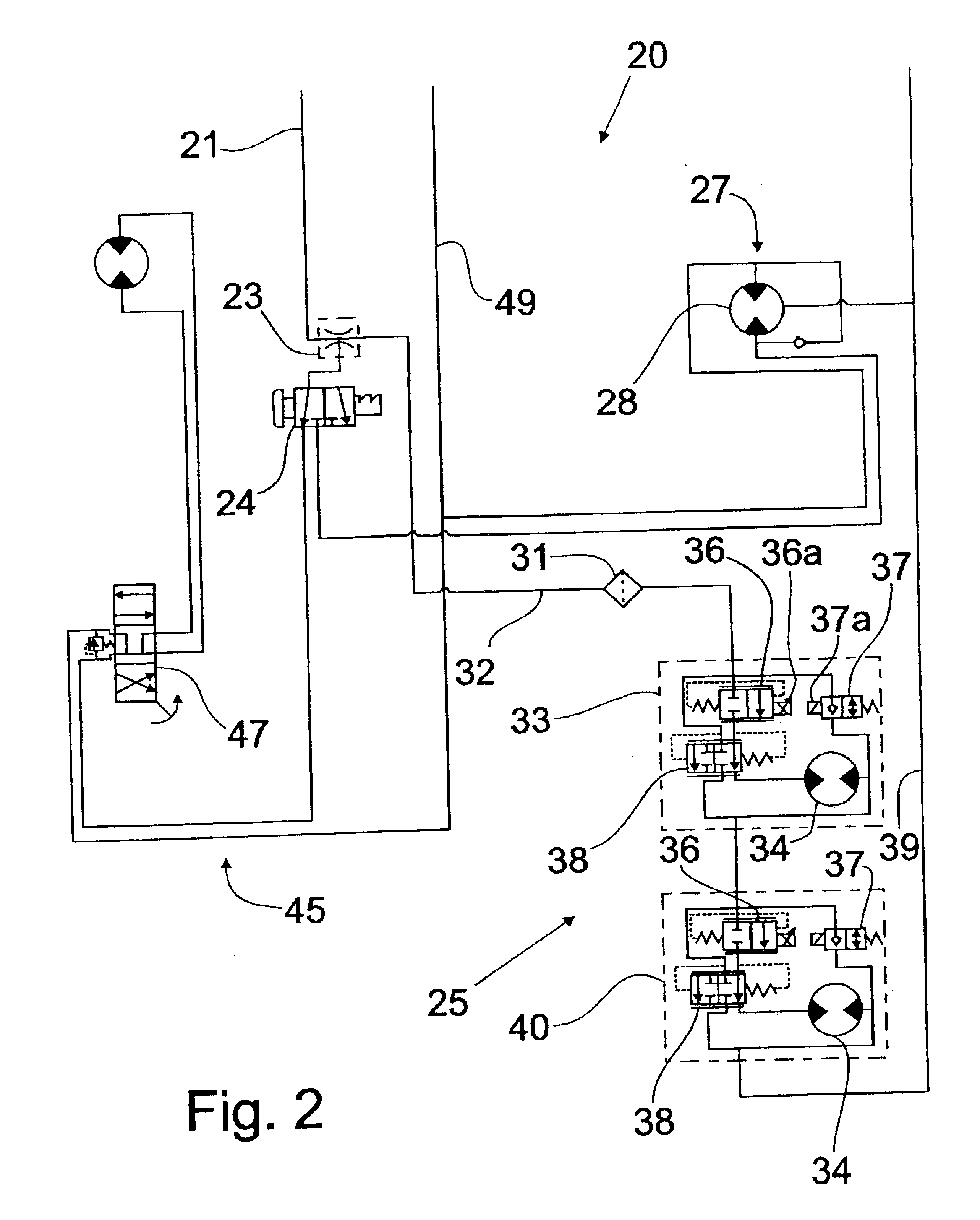
Referring first to FIGS. 1 and 2, an air seeder drive mechanism incorporating the principles of the instant invention can best be seen. An air seeder 10 is customarily attached to a tractor (not shown) in a conventional manner to provide power for both mobile movement of the air seeder over the ground G and operative power for the operation of the components of the air seeder 10, as will be described in greater detail below. The air seeder 10 is provided with a central tank 12, which can be multi-compartmental to provide storage capacity for seed, fertilizer and other products to be applied to the ground for the planting process. A fan mechanism 13 provides a source of high velocity air to be forced through distribution lines 14 coupled to the tank 12 to receive a supply of product therefrom for dispensing to the ground in a conventional manner. A metering mechanism 15 controls the flow of product into the pneumatic tubing 14 to control the rate of flow of product to the ground G. P...


PUM


Abstract

A hydraulic drive system provides a priority flow of hydraulic fluid to a variable rate drive system for powering the operation of the metering mechanisms before hydraulic fluid is supplied to a secondary drive mechanism for powering the operation of secondary devices, such as the fan mechanism or the loading auger. The hydraulic drive system includes a priority flow divider valve that diverts a predetermined flow rate to the variable rate drive system. The variable rate drive system includes a drive mechanism arranged in series for a plurality of metering mechanisms. The secondary drive system includes a selector valve that permits a selection between the alternative secondary devices. An alternative embodiment of the hydraulic drive system includes a counter balance valve that operates to provide a priority flow to the variable rate drive system.

Description

FIELD OF THE INVENTIONThe present invention relates generally to planters and air seeders for planting seeds in the ground in an agricultural environment. In particular, the present invention relates to a variable rate drive system for driving meters that dispense seeds into the air stream of an air seeder.BACKGROUND OF THE INVENTIONAs farmers continue to focus on the efficiency of their operations, interest in optimum seed and fertilizer rates has grown. This desire to optimize seed and fertilizer rates has driven technology to deliver seed, fertilizer, and other products at rates specific for the type and quality of the soil. Thus, as the soil potential changes, so does the optimum product rate. Development in this technology has focused on control systems for agricultural metering systems and on meter drive systems that can vary the rate independent of the speed of travel.Currently, a wide variety of metering systems are available that meter products in a rotatable fashion. These...

Claims


Application Information

Patent Timeline
Patent Type & Authority Patents(United States)
IPC IPC(8): A01C7/08A01C19/00A01C19/02F15B11/16F15B11/00
CPCA01C7/081A01C19/02F15B11/162F15B2211/30595F15B2211/3127F15B2211/4053Y10S111/921F15B2211/50563F15B2211/5154F15B2211/7058F15B2211/7142F15B2211/781F15B2211/50518
Inventor MAYERLE, DEANBURNS, DUSTIN G.
Owner CNH IND CANADA
Why Eureka
Try Eureka