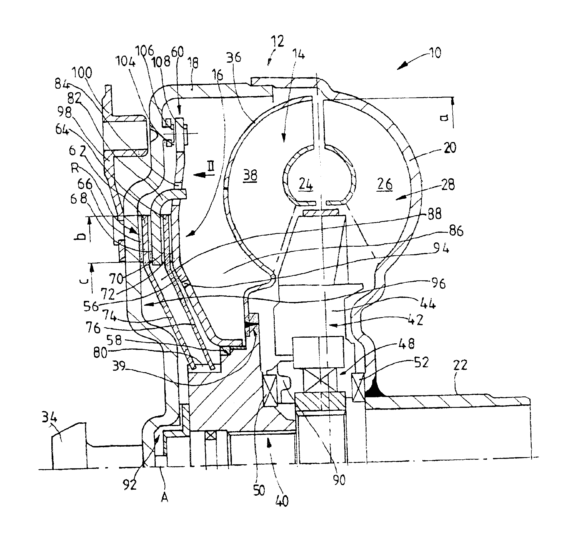
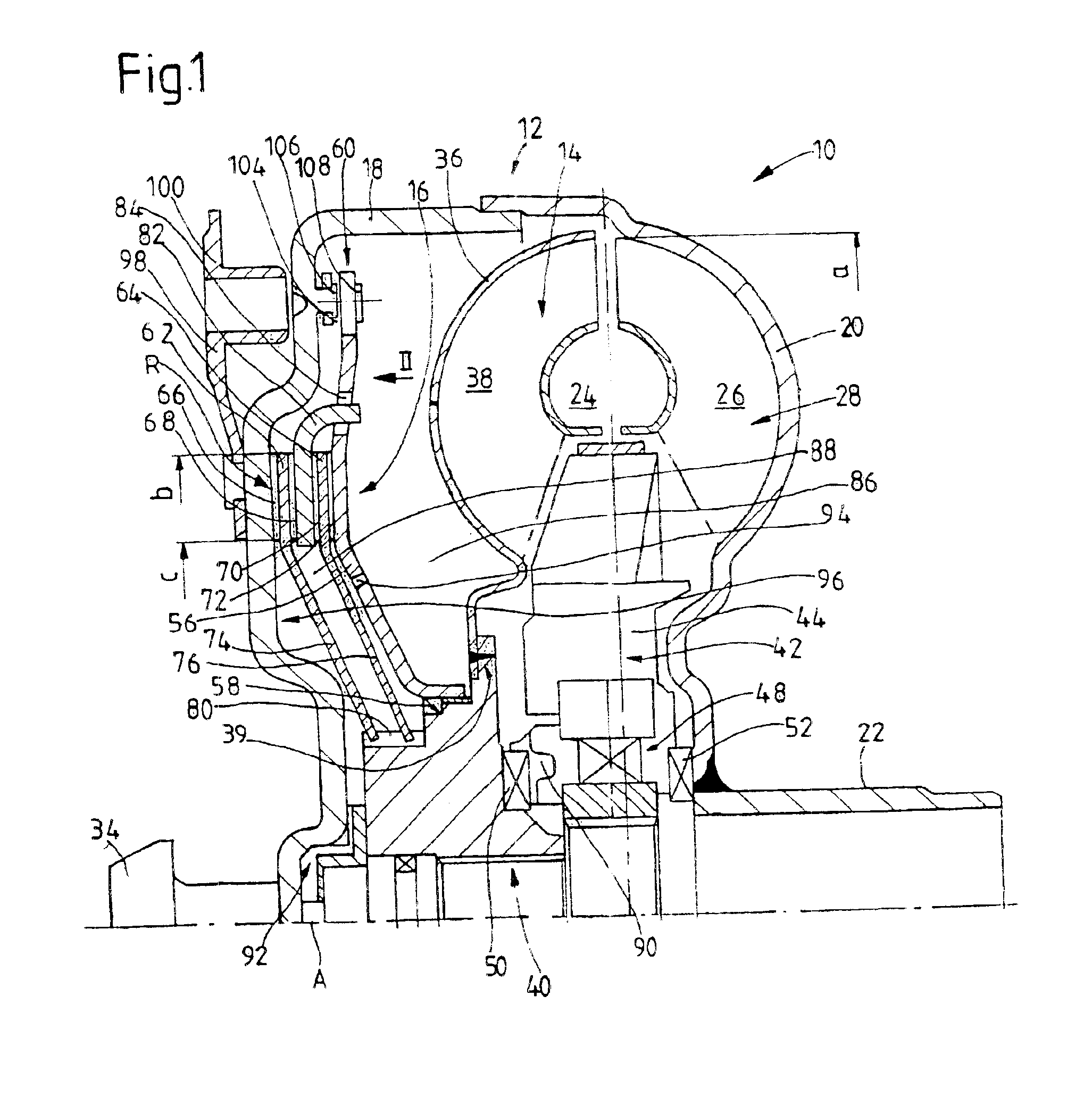
In the coupling device according to the invention, the joining of the contact element radially outside the friction surface region provides the possibility, without a significant additional outlay, of connecting the friction element or friction elements to the turbine wheel in a substantially simpler manner. In particular, the friction elements can be joined to the turbine wheel without going around the radially outer circumference of the contact element, with the result that the
mass of the coupling device and the
mass moment of
inertia of the turbine wheel are kept small.
The contact element can preferably be displaced axially on the turbine wheel and is mounted rotatably relative to the turbine wheel. This avoids a projection of the housing arrangement or an additional component provided in known coupling devices for the mounting of the contact element. In view of the contact element being driven by pressurization, this measure also permits a fluid seal between the inner circumference of the contact element and the turbine wheel. The contact element is preferably mounted here on the circumferential surface of a hub of the turbine wheel.
A particularly simple construction is produced if the at least one friction element is connected to the turbine wheel, if desired via a torsional vibrational
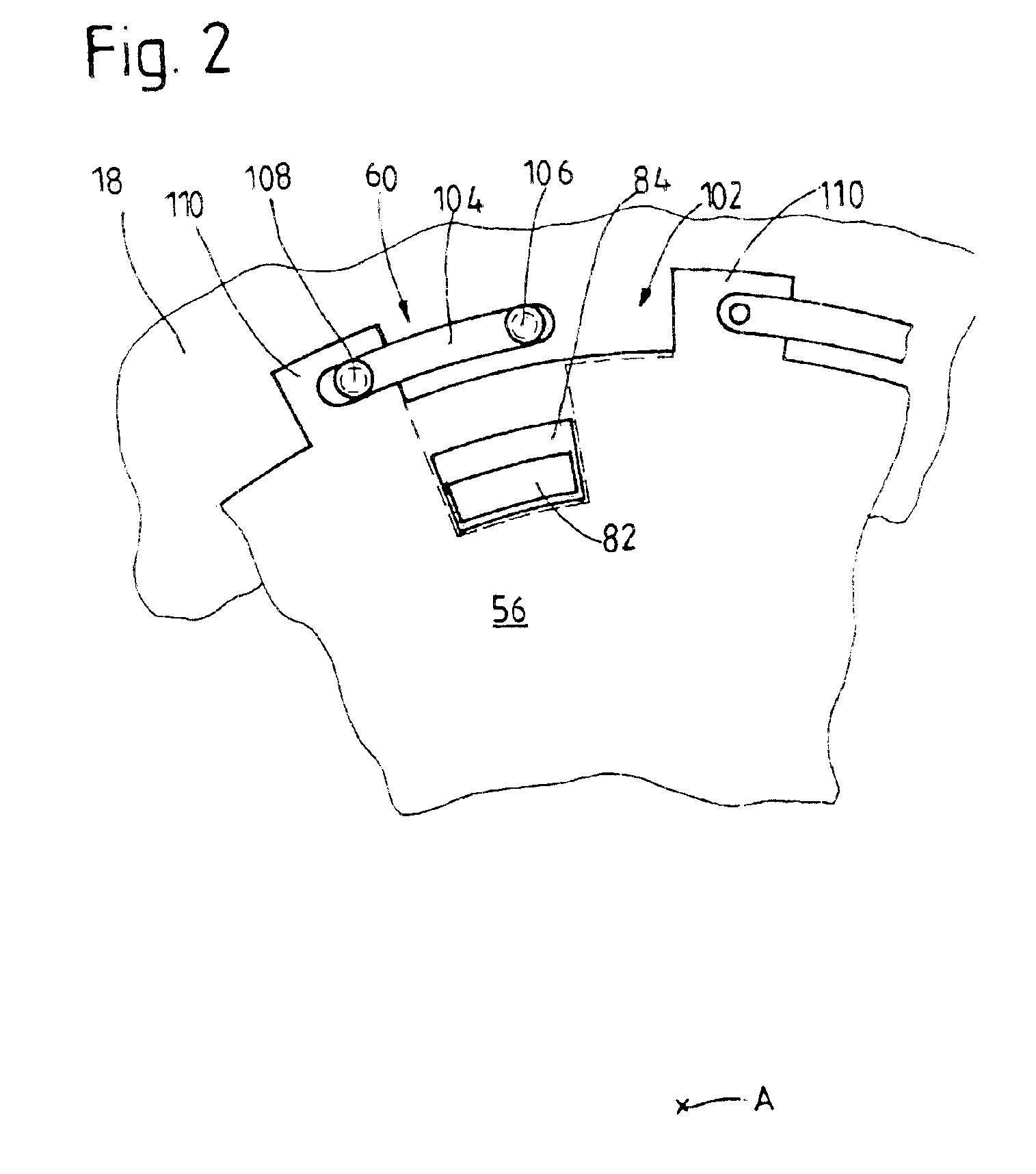
damper, radially within the friction surface region in a manner such that they essentially rotate together. For example, the friction element may comprise a friction element carrier section which extends radially inward from the friction surface region. If a plurality of friction elements are provided, each of these elements may have a friction element carrier section running in this manner. However, it is also conceivable for a friction element carrier section to be provided which extends radially inward, is common to the friction elements and is connected at its inner circumference to the turbine wheel, in particular the turbine wheel hub, and, at its outer circumference, bears a friction element driver for carrying along the individual friction elements, in particular for carrying them along in a form-fitting manner. A common friction element carrier can be connected to the turbine wheel by means of a welded joint. It should be noted here that, if there is a welded joint in the region of the turbine wheel hub, any deformation in the region of the turbine wheel shell is advantageously avoided.
In one embodiment, a plurality of friction elements is provided, an intermediate friction element, which is connected to the contact element in a manner such that they essentially rotate together, being arranged in each case between the friction surface regions of two mutually adjacent friction elements. The connection to the contact element in a manner such that they essentially rotate together ensures in a simple manner that the intermediate friction element is carried along when the housing arrangement is rotated. Each intermediate friction element or an intermediate friction element carrier common to a plurality of intermediate friction elements extends in a manner such that it engages in carry-along cutouts of the contact element. In a development of this embodiment, the carry-along cutouts are formed by radial indentations (already mentioned above) on the outer circumference of the contact element thus giving them a further function.
A construction which can be realized in a particularly simple manner for a hydrodynamic coupling device operating on the principle of a dual line
system can be obtained by an
interior space of the housing arrangement being divided by the contact element into a first spatial region in which the turbine wheel is arranged, and into a second spatial region, and by it being possible, in order to replace
working fluid provided in the
interior space, for
working fluid to be introduced into the first spatial region and for
working fluid to be removed from the second spatial region, or vice versa. In order, in a
system of this type, to permit an exchange of fluid in
spite of a radially outer sealing of the contact element by the friction surface regions resting on one another in the engaged state of the lockup clutch arrangement, it is proposed to provide at least one fluid passage opening in the contact element radially within the friction surface region to permit an exchange of fluid between the first spatial region and the second spatial region. Furthermore, in order to improve cooling of the fluid in the engaged or slipping state, it is furthermore proposed that a flow duct arrangement preferably designed with a curved shaping is provided in the friction surface region of the at least one friction element. This flow duct arrangement is preferably open toward the two spatial regions, so that a difference in pressure present in any case in these clutch states between the two spatial regions makes it possible for fluid to pass through the flow duct arrangement and, in the process, the
thermal energy arising in this spatial region can be efficiently dissipated.

