Method and apparatus for grinding workpiece surfaces to super-finish surface with micro oil pockets

a technology of workpiece surface and oil pocket, which is applied in the direction of grinding machine components, grinding machine components, manufacturing tools, etc., can solve the problems of affecting the life of the machine, the prone to bearing member seizure of the crankpin and the journal, and the disadvantageous unavoidable machining time, so as to achieve a high degree of rotational accuracy, prolong the life of use, and improve the quality of surface roughness

Inactive Publication Date: 2005-02-08
TOYODA MASCH WORKS LTD
View PDF12 Cites 6 Cited by
  • Summary
  • Abstract
  • Description
  • Claims
  • Application Information

AI Technical Summary

Benefits of technology

With the method and apparatus according to the present invention, forming the micro oil pockets on the super-finish surface of the workpiece is attained by the combination of a finish grinding and a super-finish grinding. Therefore, the super-finish surface of the workpiece is given a high quality of surface roughness wherein micro oil pockets are formed on a smooth surface finished up with a super-finish grinding wheel. When the workpiece machined by the method according to the present invention is assembled in a bearing member, the micro oil pockets on the workpiece surface serves to retain lubricating oil and to supply the oil to the friction area between the workpiece and the bearing member. Thus, the workpiece given the micro oil pockets according to the present invention assures the bearing assembly a high degree of rotational accuracy as well as a longer life of use. Further, a lapping process on a lapping machine is no longer essential, so that the workpiece can be finished in a shorter machining time and at a lower machining cost.

Problems solved by technology

Due to lack of micro oil pockets, such lapped surfaces of the crankpins and journals are liable to suffer from seizure to bearing members therefor.
Further, since the crankpins and journals are ground on a grinding machine and then, are lapped on a lapping machine, a longer machining time as well as a higher cost for the machining facilities are disadvantageously unavoidable.

Method used


Image

  • Method and apparatus for grinding workpiece surfaces to super-finish surface with micro oil pockets
  • Method and apparatus for grinding workpiece surfaces to super-finish surface with micro oil pockets
  • Method and apparatus for grinding workpiece surfaces to super-finish surface with micro oil pockets

Examples


Embodiment Construction

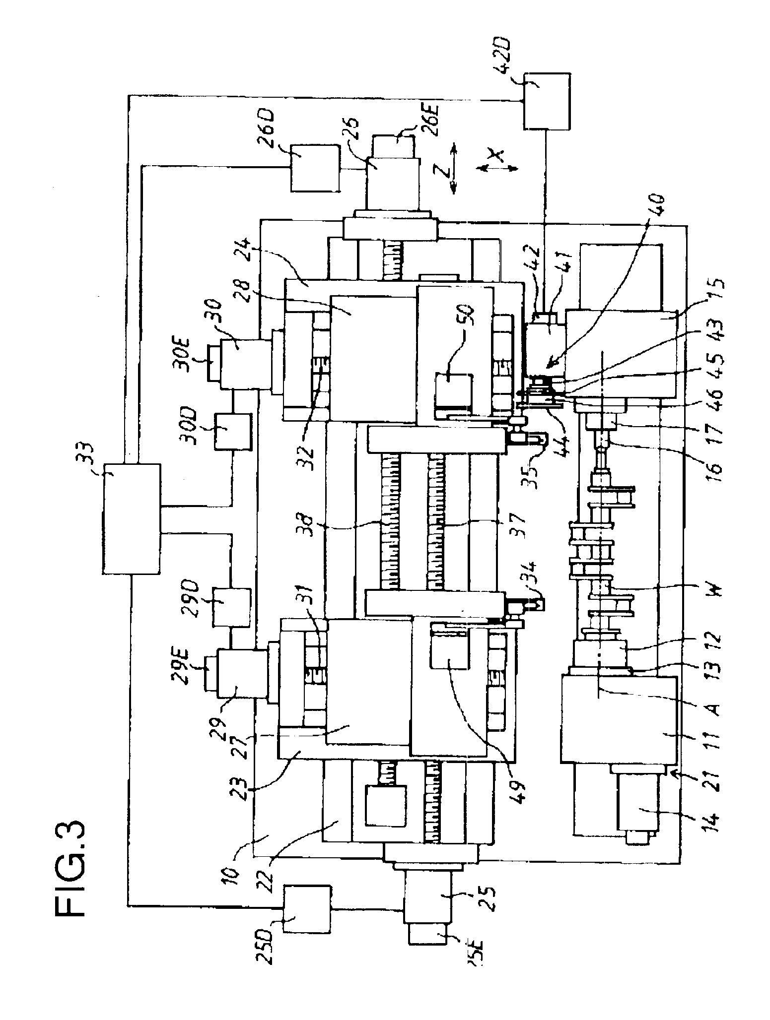
A grinding machine for grinding workpieces surfaces to super-finish surfaces with micro oil pockets according to the present invention will be described hereafter with reference to the accompanying drawings. Referring now to FIG. 3, a numeral 10 denotes a bed 10 of the machine, on which a work head 11 is fixed at a front-left position. A work spindle 13 having a chuck 12 mounted at its end is born in the work head 11 and is rotatable by a work spindle motor 14 about a rotational axis A. A numeral 15 denotes a tail stock, which is fixed at a front-right position on the bed 10 in face-to-face relation with the work head 11 and is adjustable toward and from the work head 11. A ram 17 having a center 16 fitted in its end is received in tail stock 15 for sliding movement on the aforementioned rotational axis A. The ram 17 is urged by means of a compression spring, not shown, toward the work head 11.

The workpiece W in the form of e.g., a crankshaft is grasped at its one end by the chuck 1...


PUM

PropertyMeasurementUnit
thickaaaaaaaaaa
sizeaaaaaaaaaa
surface roughnessaaaaaaaaaa

Abstract

A grinding machine rotatably carrying a finish grinding wheel and a super-finish grinding wheel respectively on first and second wheel heads practices a method of grinding workpiece surfaces to super-finish surfaces with micro oil pockets. A surface of a workpiece rotatably carried on the machine is first ground with the finish grinding wheel to a predetermined diameter under the control of a sizing device. The workpiece surface is then ground with the super-finish grinding wheel to a target diameter under the control of a sizing device. The super-finish grinding is performed to the extent that peaks of a section curve representing the roughness of the workpiece surface attained by the finish grinding are removed but bottoms of the surface curve are left to a depth when the target diameter is reached, so that the bottoms so left of the roughness constitute the micro oil pockets.

Description

INCORPORATION BY REFERENCEThe present application claims priority under 35 U.S.C. .sctn.119 to Japanese Patent Application No. 2001-297919, filed on Sep. 27, 2001. The contents of that application are incorporated herein by reference in its entirety.BACKGROUND OF THE INVENTION1. Field of the InventionThe present invention relates to methods and apparatus for grinding a surface of a workpiece to a super-finish surface with micro oil pockets by grinding the workpiece surface with a super-finish grinding wheel after a finish grinding with a finish grinding wheel.2. Description of the Related ArtHeretofore, crankpins and journals of crankshafts have been ground with a finish grinding wheel on a grinding machine and then, have been lapped on a lapping machine for improved surface roughness. The surfaces of the crankpins and journals after the lapping process have a roughness of the order which ranges from 0.4 through 0.8 μmRzISO. As shown in FIG. 1, the section curve representing the rou...

Claims


Application Information

Patent Timeline
Patent Type & Authority Patents(United States)
IPC IPC(8): B24B27/00B24B5/00B24B53/04B24B53/053B24B49/00B24B5/42B24B49/04B24B51/00B24B53/00
CPCB24B5/42B24B53/053B24B49/00B24B27/0076
Inventor ITO, NAOKIKATSUTA, MAMORUSOMA, SHINJISUGIYAMA, KAZUHISA
Owner TOYODA MASCH WORKS LTD
Why Eureka
Try Eureka