

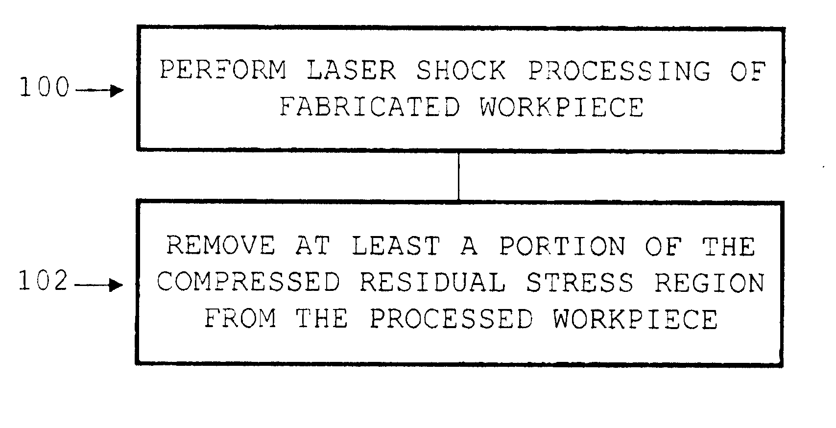
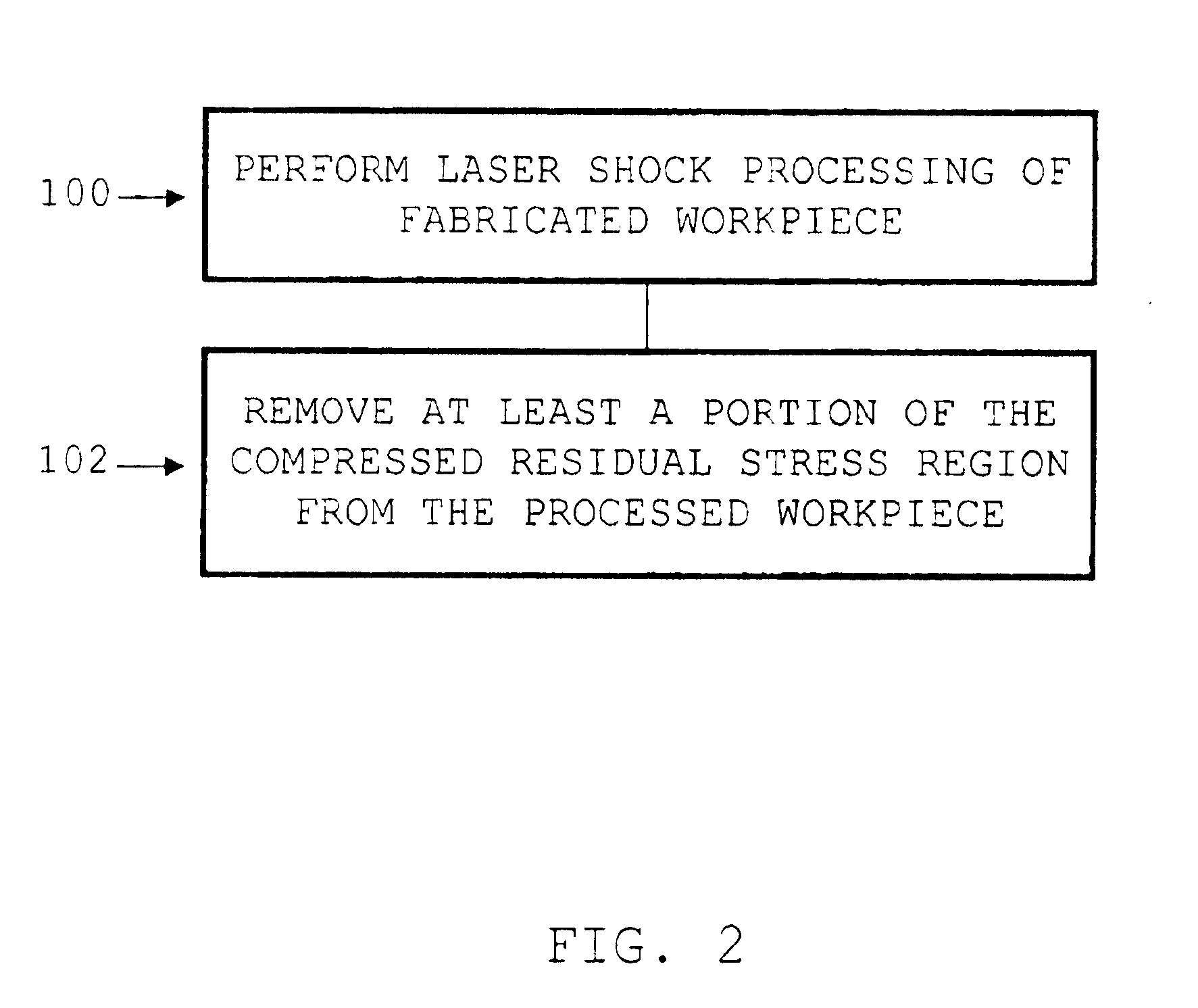
Method of modifying a workpiece following laser shock processing
a technology of laser shock processing and workpiece, which is applied in the direction of laser beam welding apparatus, manufacturing tools, transportation and packaging, etc., can solve the problems of surface roughness and partially rolled-over or extruded edges, surface geometry irregularities, and distortion of the shape of parts, so as to improve the fatigue properties of parts
- Summary
- Abstract
- Description
- Claims
- Application Information
AI Technical Summary
Benefits of technology
Problems solved by technology
Method used
Image

Examples
Embodiment Construction
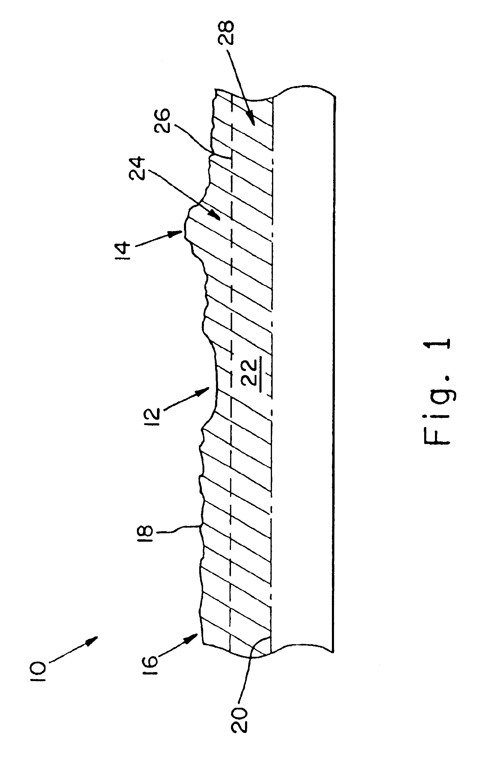
By way of overview, the various processing methods disclosed herein involve processing activities that are preferably executed upon a workpiece, article, or other such part following the performance of a laser shock processing operation on the workpiece. Stated otherwise, the various part modification procedures disclosed herein are carried out on a previously processed workpiece.
The manner of conducting such laser shock processing does not form an essential part of the present invention as it should be apparent that the workpiece can be subjected to any suitable type of laser peening conditions. Additionally, the processed condition of the workpiece may be generated in accordance with any activity involving, inter alia, laser shock processing, shot peening, the application of a force or pressure field to the workpiece, or the development of stress regions within the workpiece.
The various part modification procedures of the present invention individually endeavor in a general way to...
PUM
| Property | Measurement | Unit |
|---|---|---|
| surface roughness | aaaaa | aaaaa |
| depth | aaaaa | aaaaa |
| compressive residual stress | aaaaa | aaaaa |
Abstract
Description
Claims
Application Information