Trench capacitor with buried strap

Inactive Publication Date: 2005-02-08
POLARIS INNOVATIONS
View PDF7 Cites 10 Cited by
  • Summary
  • Abstract
  • Description
  • Claims
  • Application Information

AI Technical Summary

Benefits of technology

By forming the strap on a planar surface, the divot present in conventional strap pro

Problems solved by technology

However, due to the small dimensions of the divot and to the non-ideal conformal deposition of the amorphous silicon layer, a void 277 may be created during the divot fill process.
The void re

Method used


Image

  • Trench capacitor with buried strap
  • Trench capacitor with buried strap
  • Trench capacitor with buried strap

Examples


Embodiment Construction

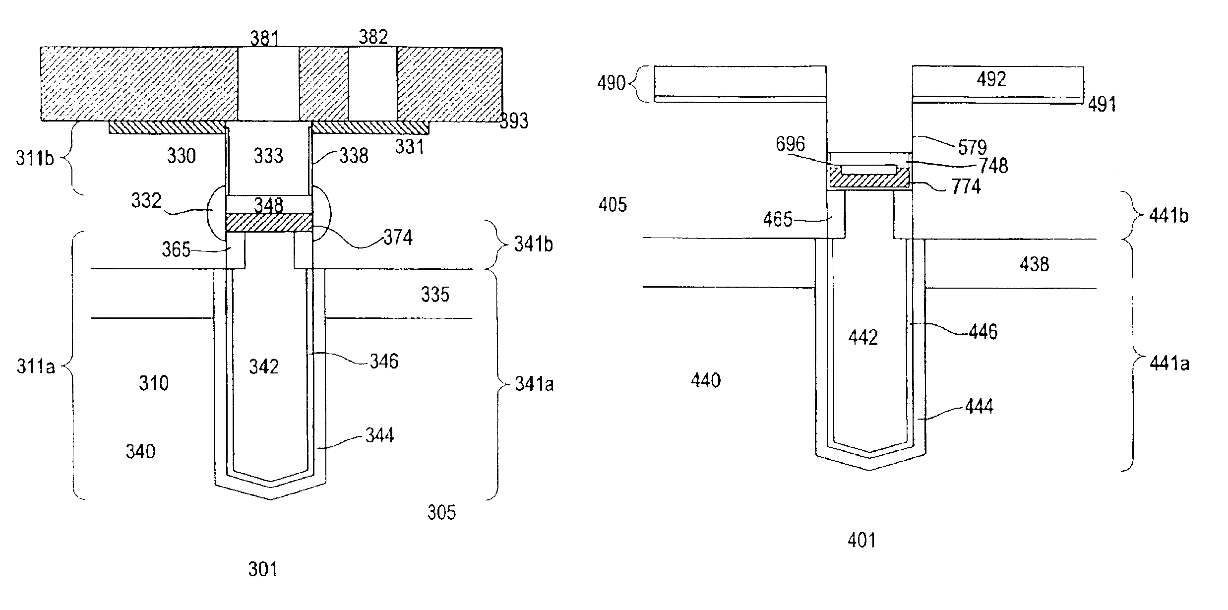
FIGS. 3a-b show a schematic diagram and a cross-sectional view of a memory cell 301 in accordance with one embodiment of the invention. The memory cell includes a trench capacitor 340 coupled to a transistor 330. A first diffusion region of the transistor is coupled to a bitline 380 and a gate 333 of the transistor is coupled to a wordline 385. A plurality of memory cells are interconnected by wordlines and bitlines to form a memory array. The array and support circuitry for accessing the memory cells form, for example, a memory IC. Other types of ICs can also be formed, such as systems on chip embedded with memory.

The trench capacitor is located in a lower portion 311a of a trench 310 formed in a substrate 305. The trench capacitor comprises bottom and top sections 341a-b. A first capacitor plate 342 is located in the trench. In one embodiment, a second plate 344 is also provided. The second plate surrounds the trench in the lower section of the capacitor. The plates are separated ...


PUM


Abstract

A trench capacitor with improved strap is disclosed. The strap is located above the top surface of the capacitor. The top surface of the trench capacitor which is formed by the top surfaces of the collar and storage plate, is planar. By locating the strap on a planar surface, the divot present in conventional strap processes is avoided. This results in improved strap reliability and device performance.

Description

BACKGROUND OF INVENTIONA dynamic random access memory (DRAM) cell includes a transistor coupled to a capacitor. One type of DRAM cell employs the use of a trench capacitor coupled to a vertical transistor. FIG. 1 shows a cross-sectional view of a conventional trench capacitor 140. As shown, the trench capacitor is disposed in a lower portion 111a of a trench 110 formed in a substrate 105. A pad layer 190 is provided on the surface of the substrate. The pad layer comprises silicon nitride layer 192 over a silicon oxide layer 191. The pad layer facilitates processing of the trench capacitor.The trench capacitor includes bottom and top sections 141a-b. A buried plate 144 surrounds the trench in the bottom section of the capacitor. A highly conducting semiconductor material or metal 142 (fill material) fills the trench, separated from the buried plate by a node dielectric layer 146. The buried plate, for example, is commonly coupled to other capacitors of the array and to a reference vo...

Claims


Application Information

Patent Timeline
IPC IPC(8): H01L21/70H01L21/02H01L21/20H01L27/108H01L21/8242H01L33/00
CPCH01L27/10867H01L27/10864H10B12/0383H10B12/0385
Inventor TEWS, HELMUTBEINTNER, JOCHENKUDELKA, STEPHAN
Owner POLARIS INNOVATIONS
Why Eureka
Try Eureka