Oil quality measurement device

a technology of oil quality measurement and oil circuit, which is applied in the direction of filtration separation, instruments, separation processes, etc., can solve the problems of premature reduced lubricating ability, and deterioration of oil quality, so as to increase the precision of measurement results, increase measurement precision, and increase measurement precision

Inactive Publication Date: 2005-02-08
MANN HUMMEL GMBH
View PDF13 Cites 37 Cited by
  • Summary
  • Abstract
  • Description
  • Claims
  • Application Information

AI Technical Summary

Benefits of technology

It has been found advantageous to position the oil condition sensor on the filtered oil side of the oil filter in order to increase the measurement precision. The concentration of foreign materials in the oil is comparatively low at this location and relatively free of suspended particles. These factors favor the acquisition of a precise and accurate measurement result.
In one advantageous embodiment, the oil condition sensor is integrated into an end plate of the filter element. The end plate is contacted by a good flow of the oil to be checked and thus the end plate offers a suitable location for precise measurement. When manufactured as a separate single part, it avoids the need for structural changes to the remaining components of the oil filter.
To increase the precision of the measured result, it has been found advantageous to construct the sensor with the greatest possible geometric extent or measurement length. For this purpose, it is advantageous to use a spiral-shaped or meandering arrangement, for example, of an electrically conductive measurement wire, metal strip, or the like, as a result of which a large overall measurement length may be housed in

Problems solved by technology

In the course of operation of an oil circuit, the oil quality may deteriorate, for example, due to dirt contamination, decomposition, water absorption, or the like.
In lubricant oil circuits of internal combustion engines, soot particles, abraded metal, and even fuel, among other things, enter the oil in an undesired way and reduce its lubricating ability.
Unfavorable operating parameters, such as frequently perform

Method used


Image

  • Oil quality measurement device
  • Oil quality measurement device
  • Oil quality measurement device

Examples


Embodiment Construction

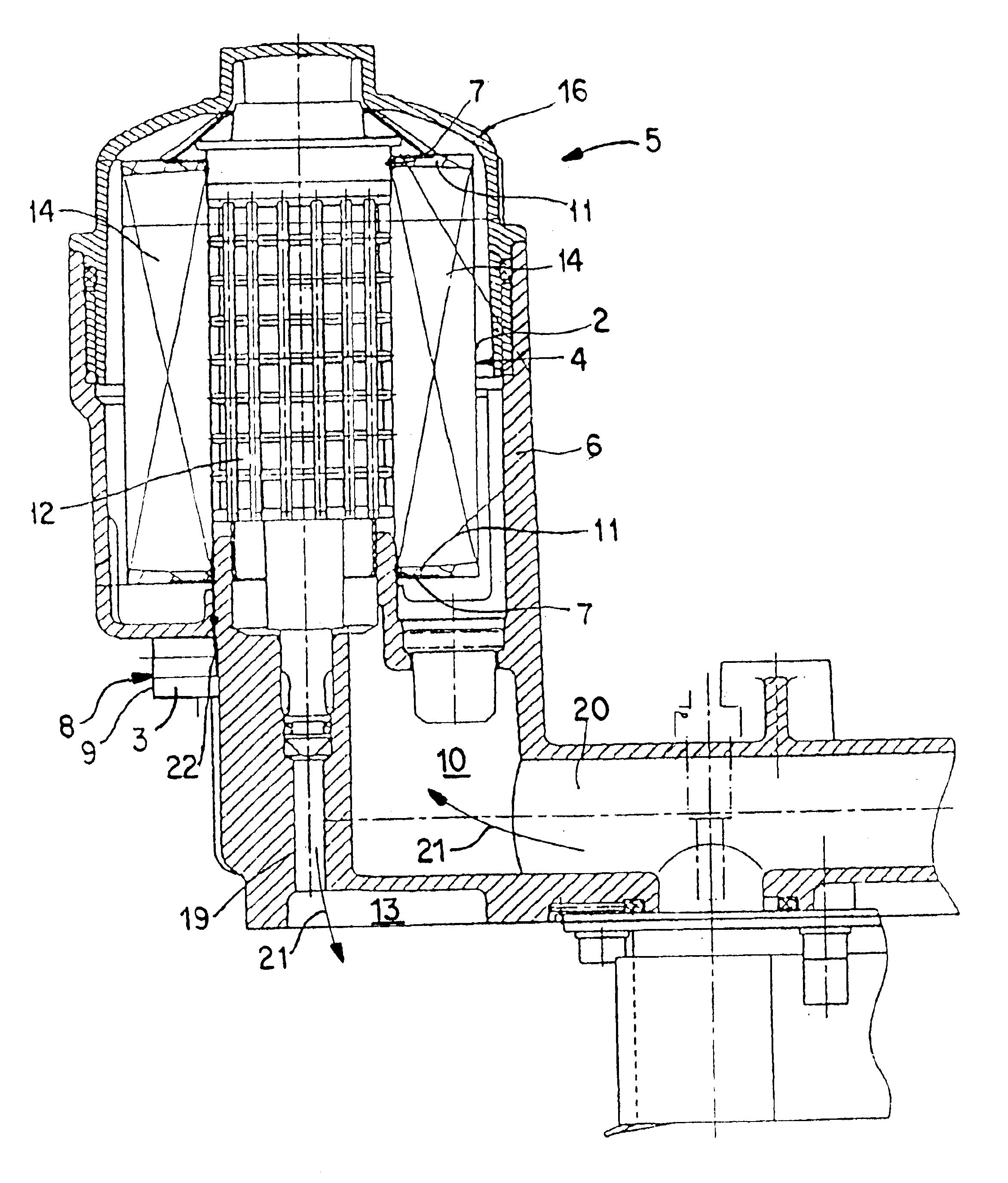
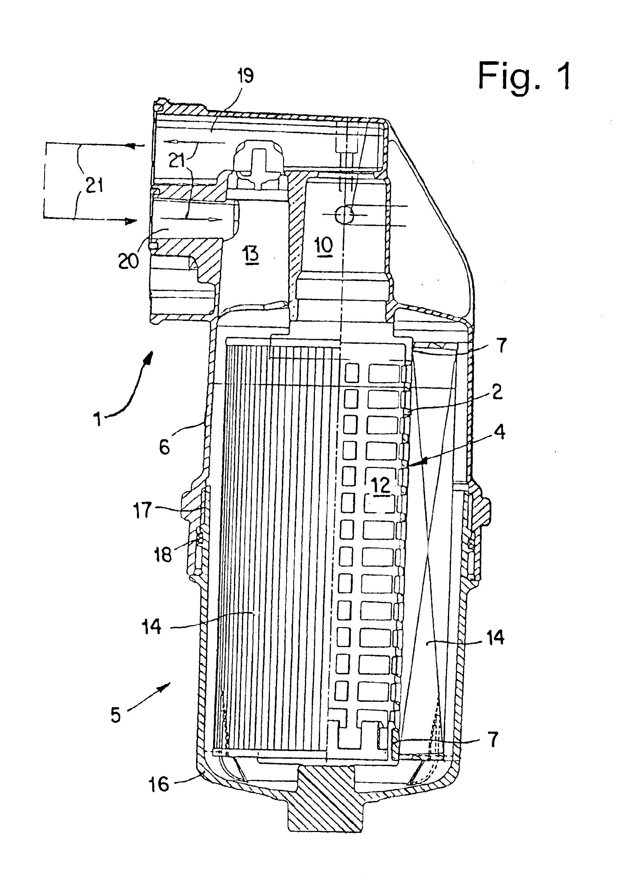
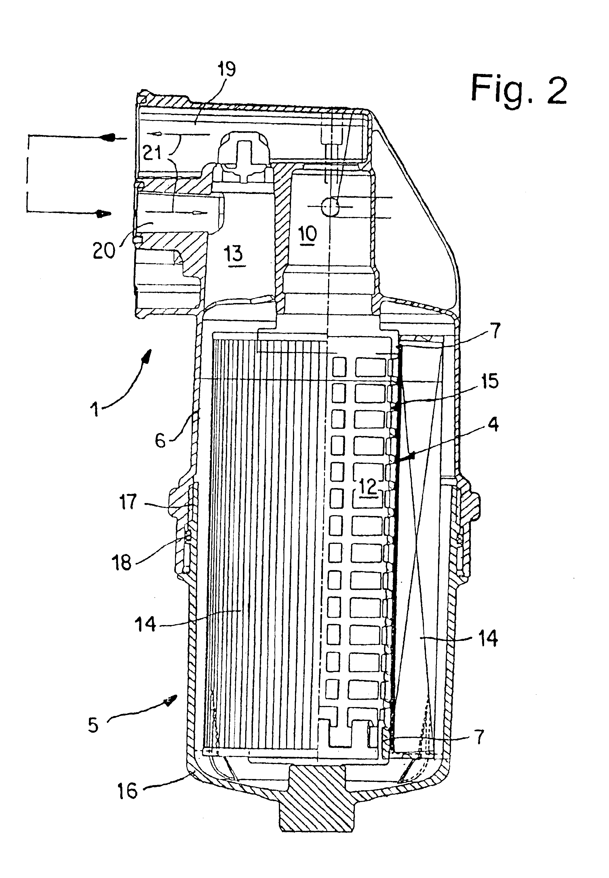
FIG. 1 shows a sectional illustration of an oil filter 5 of a schematically outlined oil circuit 1, using the example of a lubricant oil circuit for a truck diesel motor. Comparable arrangements may also be provided for lubricant oil circuits in passenger vehicles, for gear oil circuits, and for hydraulic oil circuits.

In the oil circuit 1, an oil filter 5 is provided, which, in the illustrative embodiment shown, comprises a filter housing 16 screwed into a filter receptacle 6. A cylindrical, perforate or foraminous support body 12 and a filter element 14, which is also cylindrical and which encloses the support body 12, are positioned in the filter housing 16. The support body 12 and the filter element 14 are held in the axial direction between an end wall of the filter housing 16 and the filter receptacle 6. The filter housing 16 may be screwed into the filter receptacle 6 using a thread 17 and is sealed in relation to the filter receptacle 6 via a circumferential O-ring 18.

The flo...


PUM


Abstract

An oil quality measurement device for an oil circuit (1), which includes an oil condition sensor (2) and an analysis circuit (3). The oil condition sensor (2) is constructed as a capacitive or impedance spectroscopic sensor (4) and attached to the filter element (14) in such a way that, when the filter element (14) is replaced, the oil condition sensor (2) is also automatically replaced.

Description

BACKGROUND OF THE INVENTIONThe present invention relates to an oil quality measurement device for an oil circuit.The reliable operation of an oil circuit for lubricating an internal combustion engine in a motor vehicle or a hydraulic installation, for example, requires good oil quality. In the course of operation of an oil circuit, the oil quality may deteriorate, for example, due to dirt contamination, decomposition, water absorption, or the like. In lubricant oil circuits of internal combustion engines, soot particles, abraded metal, and even fuel, among other things, enter the oil in an undesired way and reduce its lubricating ability.To maintain a specific oil quality over a predetermined cycle, an oil filter, which serves to filter contaminants which arise out of the oil, is arranged in the oil circuit. Particularly during the operation of diesel motors, corrosive acids may arise in the oil, for whose neutralization appropriate metallic materials are positioned in the oil filte...

Claims


Application Information

Patent Timeline
IPC IPC(8): G01N33/28G01N33/26G01N27/02G01N27/22B01D35/143
CPCB01D29/60B01D35/143G01N33/2888G01N27/226G01N27/02
Inventor BEYLICH, MARKUSFRANZ, ANDREAS
Owner MANN HUMMEL GMBH
Why Eureka
Try Eureka