Delay locked loop circuit with duty cycle correction function

Inactive Publication Date: 2005-02-08
SK HYNIX INC
View PDF3 Cites 153 Cited by
  • Summary
  • Abstract
  • Description
  • Claims
  • Application Information

AI Technical Summary

Benefits of technology

Preferably, the DLL circuit further comprises a first phase splitter for receiving the output clock signal and generating a first phase-split output clock signal and a second phase-split output clock signal having a phase difference of 180°. The DCC integration

Problems solved by technology

Such a method has an advantage of obtaining a high level of correctness but has a disadvantage of increasing errors as a frequency becomes lower because locking time is long and an applicable bandwidth is not very wide.
Howe

Method used


Image

  • Delay locked loop circuit with duty cycle correction function
  • Delay locked loop circuit with duty cycle correction function
  • Delay locked loop circuit with duty cycle correction function

Examples


Embodiment Construction

Hereinafter, a preferred embodiment of the present invention will be described with reference to the accompanying drawings. In the following description and drawings, the same reference numerals are used to designate the same or similar components, and so repetition of the description on the same or similar components will be omitted.

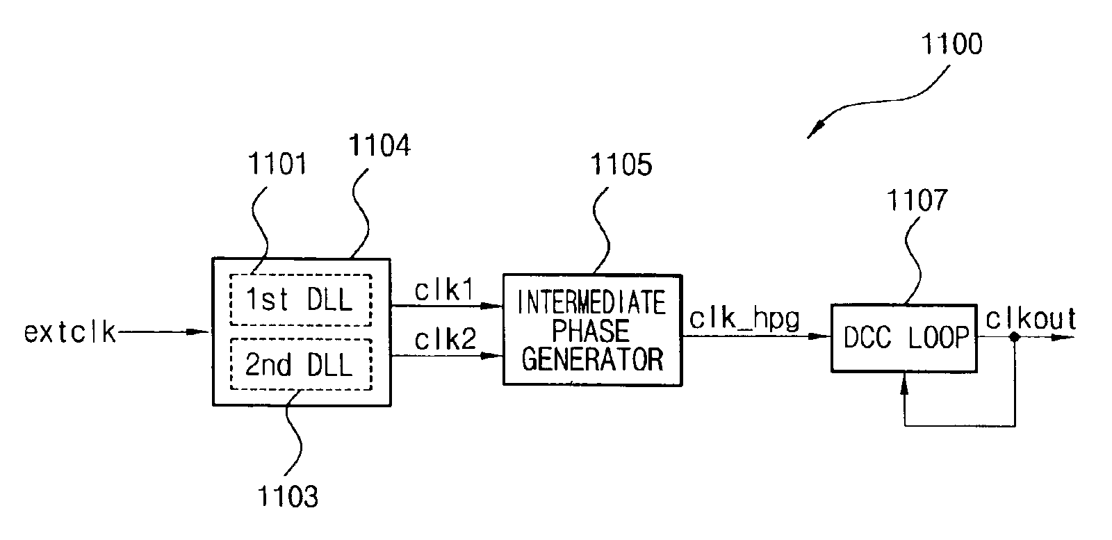
FIG. 11 is a block diagram of a delay locked loop (DLL) circuit with a duty cycle correction (DCC) function according to an embodiment of the present invention. As illustrated in FIG. 11, a DLL circuit according to the present embodiment includes a DLL block 1104 including two DLLs 1101 and 1103, an intermediate phase generator 1105, and a DCC loop 1107. That is, a conventional DCC circuit including the two DLLs 1101 and 1103 and the intermediate phase generator 1105 and a conventional DCC circuit including the DCC loop 1107 are combined with each other.

The circuit of FIG. 11 operates as follows. A front part including the two DLLs 1101 and 1103 and the...


PUM


Abstract

A delay locked loop (DLL) circuit having a structure in which a method of performing duty cycle correction (DCC) using two DLLs and an intermediate phase composer and a method of performing DCC by forming a closed loop using a negative feedback are combined with each other is provided. The DLL circuit includes a first DLL for receiving an external clock signal and generating a first clock signal and a second DLL for receiving an external clock signal and generating a second clock signal. The first clock signal and the second clock signal are synchronized with an external clock signal. The DLL circuit further includes an intermediate phase generation circuit for receiving the first and second clock signals and generating an intermediate phase clock signal and a DCC loop for receiving the intermediate phase clock signal and generating an output clock signal. The intermediate phase clock signal has an intermediate phase between the phases of the first and second clock signals. The output clock signal is generated through correction of the duty cycle of the intermediate phase clock signal using a value obtained by integrating the output clock signal.

Description

BACKGROUND OF THE INVENTION1. Field of the InventionThe present invention relates to a delay locked loop circuit with a duty cycle correction function.2. Description of the Prior ArtAs generally known in the art, the present invention may particularly be applied to semiconductor memory apparatuses requiring delay locked loop circuits, however, it may also be used for all kinds of semiconductor apparatuses and computer systems requiring delay locked loop circuits.A delay locked loop (DLL) is a clock generating apparatus for compensating for skew between an external clock and data or an external clock and an internal clock. A conventional DLL with a duty cycle correction (DCC) function is divided into two methods of application. One is a method of realizing negative feedback using a DCC integrator. The other is an open loop method without feedback only in a DCC aspect, in which one more DLL is used.FIG. 1 is a block diagram of a DLL circuit with a DCC loop realized by the first method...

Claims


Application Information

Patent Timeline
IPC IPC(8): H03K5/13H03K5/15H03K5/151H03K5/156H03L7/081H03L7/07H03L7/08H03K5/00H03L7/00
CPCH03K5/151H03K5/1565H03K5/133H03L7/07H03L7/0812H03K2005/00039H03L7/00
Inventor LEE, SEONG HOON
Owner SK HYNIX INC
Why Eureka
Try Eureka